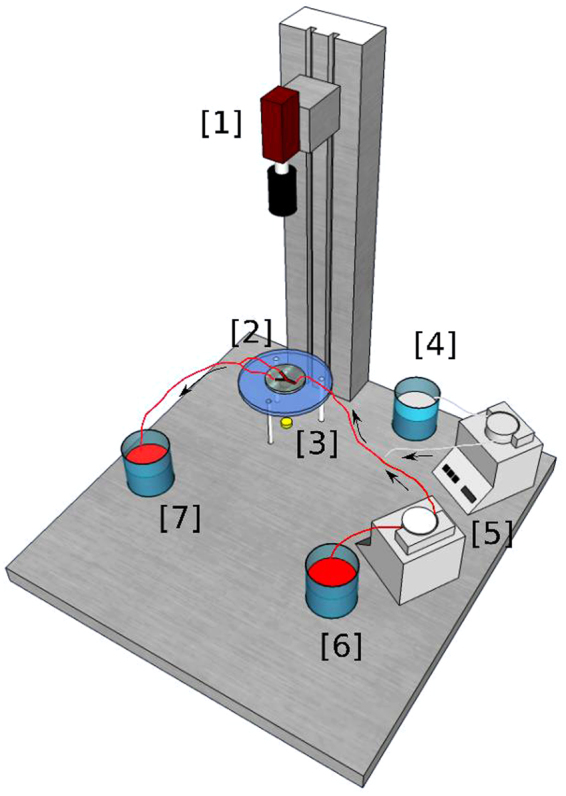
Figure 4.

General scheme of the experimental setup. Two peristaltic pumps are used to pump ferroin and sucrose solution from their corresponding reservoirs. The mixture of both fluids occurs in a Y-shaped bifurcation and after that, the mixture enters the PDMS geometry that is illuminated with a LED. There, the flow is registered by a CCD camera. Finally, the mixture exits to a third reservoir. [1] CCD Camera, [2] PDMS Geometry, [3] LED, [4] Reservoir (Sucrose Solution), [5] Peristaltic Pumps, [6] Reservoir (Ferroin), [7] Reservoir (Ferroin + Sucrose Solution).
