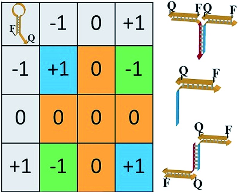
 Ternary computing, beyond Boolean logic, is anticipated to enhance computational complexity. DNA-based ternary computing is demonstrated by the assembly of a 3 × 3 multiplication table, and the parallel operation of three 3 × 3 multiplication matrices is highlighted.
Abstract
Non-Boolean computations implementing operations on multi-valued variables beyond base 2 allow enhanced computational complexity. We introduce DNA as a functional material for ternary computing, and in particular demonstrate the use of three-valued oligonucleotide inputs to construct a 3 × 3 multiplication table. The system consists of two three-valued inputs of –1; 0; +1 and a fluorophore/quencher functional hairpin acting as computational and reporter module. The interaction of the computational hairpin module with the different values of the inputs yields a 3 × 3 multiplication matrix consisting of nine nanostructures that are read out by three distinct fluorescence intensities. By combining three different hairpin computational modules, each modified with a different fluorophore/quencher pair, and using different sets of inputs, the parallel operation of three multiplication tables is demonstrated.
The information encoded in the base sequence of DNA dictates instructive paths for the programmed reconfiguration of DNA structures using the strand displacement mechanism, energetically favored hybridization and cooperative assembly of duplex nanostructures.1 These features of oligonucleotides led to the use of DNA as a functional material for the self-assembly of DNA nanostructures,2 for tailoring of DNA machines,3 and for the application of DNA for computational operations.4 Numerous studies have implemented DNA to construct logic gates,5 nucleic acid based automata6 and DNA-driven computational circuitries.7 Nonetheless, in all of these systems the paradigm of Boolean logic gates has been implemented, where binary inputs activate the logic operations that lead to TRUE or FALSE outputs. The complexity of computational circuitries in these systems was achieved by cascading logic gates,8 by branching logic processes and adapting thresholds,9 and by the selective, guided interactions of the inputs with libraries of oligonucleotides that provide computing modules.10
The development of DNA computing circuitries based on Boolean logic suffers, however, from several basic limitations: the implementation of cascaded logic gates is accompanied by a stepwise decrease in the intensity and the rate of formation of the output signal, and hence, feedback amplification paths were suggested to overcome these difficulties.11 Furthermore, the increase in the complexity of computing circuits requires an increase in the number of oligonucleotides in the system. Consequently, undesirable cross-interactions between the components occur, and these could lead to leakage phenomena that may slow down the computing circuit, generate perturbing high background signals, and eventually limit the practical applicability of the systems.
It was suggested that non-Boolean, ternary computations, implementing base integers beyond two (binary arithmetic), could be more efficient, economical and allow substantially higher computational complexity.12 The implementation of multi-value computational systems, and particularly molecular ternary computing, is, however, scarce.13 Schemes for multiplication of three-valued signals and logic gates were proposed on quantum dots.14 Also, it was demonstrated that charge quantization of a multi-gate silicon metal-on-insulator single electron transistor could be utilized to perform ternary addition.15 The use of DNA as a functional material for ternary computation is particularly interesting since the use of multi-valued DNA computing systems might reduce the number of nucleic acid strands in the system, thereby minimizing cross-interactions and enhancing the computing rates, while increasing the complexity of the system. In the present study, we implement a three-valued input(s) driven DNA computing system, consisting of a functional DNA hairpin structure that acts as a computational and reporter module, to construct a three-valued matrix multiplication table. We further demonstrate the operation of three multiplication tables in parallel. Previous studies have addressed the assembly of binary multiplication tables using the strand displacement principle.16 Nonetheless, as far as we are aware, the use of DNA for ternary computing has never been demonstrated, and this study adds a new dimension to DNA biocomputing. For a 3 × 3 multiplication matrix, the number of pairs of inputs is n2 = 9 (in contrast to the four computation pairs of inputs for Boolean variables), and by operating the three matrices, the system processes 27 pairs of inputs (in contrast to 12 pairs of three binary matrices). The present system not only introduces DNA for ternary computing but might also have important implications for clinical diagnostics. For example, different diseases are reflected by different gene expressions, and thus the identification of specific gene patterns by three-valued matrices could provide a rapid and effective diagnostic tool.
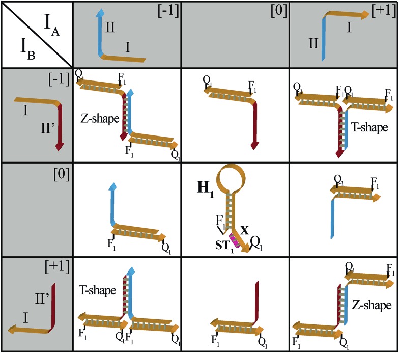
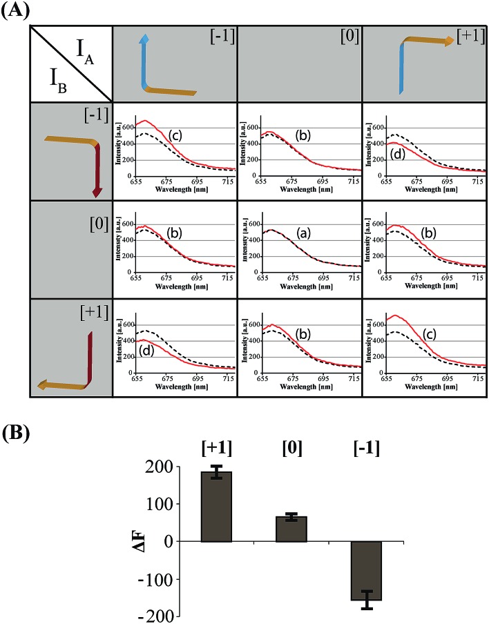
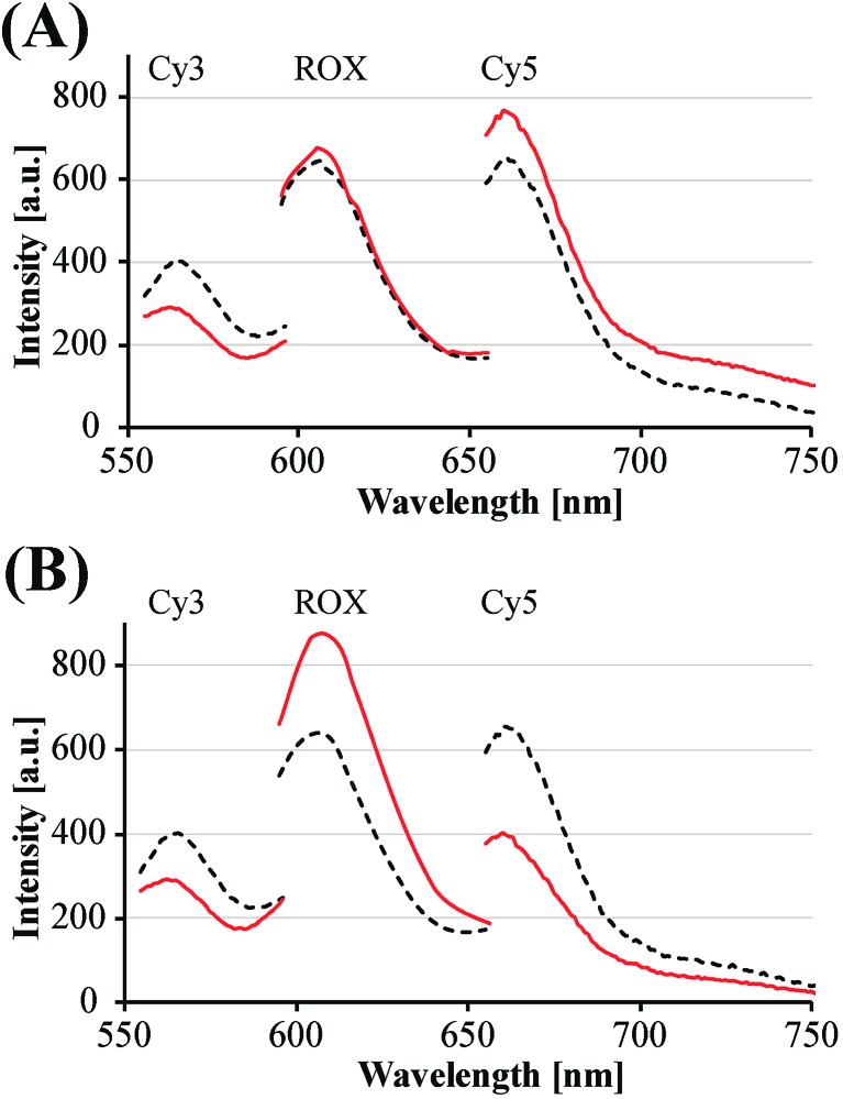
The principles to construct a DNA based three-valued multiplication matrix are depicted in Fig. 1: (i) the system is based on a hairpin structure (H1) that acts as the computational module. The hairpin (H1) is functionalized at its ends with fluorophore (F1) and quencher (Q1) units. The fluorophore provides the fluorescence signal as output for the computation; (ii) each of the two inputs (IA/IB) exists in three values, [–1]; [0]; [+1]. Each of the inputs fulfills several important features that allow their integration in the multiplication matrix: (a) each of the inputs IA or IB includes a domain “I” that can interact with the hairpin computing module (H1) and opens it; (b) the inputs IA and IB include the domains II and II′, respectively, that are complementary to one another; (iii) the three values of the inputs are generated by the internal exchange of the domains in the input values. For input IA, the value [–1] includes the domains I and II in the directionality 5′ → 3′, while the value [+1] consists of the transposed domains I and II. For input IB, which includes domains I and II′, the value [–1] includes domains I and II′ in the directionality 5′ → 3′, and for the value [+1] these domains are transposed. The value [0] for the two inputs represents the input-lacking complex; (iv) the 3′-end of the stem region of the hairpin (H1) exists in a single-strand overhang configuration, domain “X”, which is stretched by the strand (ST1), exhibiting a partial complementarity to domain “X”. The stretcher is introduced to rigidify the free quencher-functionalized tether of the hairpin. The interactions of the different values of the two inputs with the computing module result in the multiplication operation leading to the different nucleic acid nanostructures shown in Fig. 1. The read out of the computational multiplication of the pairs of inputs is provided by the fluorescence output of the system and this is displayed in Fig. 2. The fluorescence of F1 in the hairpin structure corresponds to the product [0] × [0] (Fig. 2, curve (a)). The products [0] × [–1] and [+1] × [0] result in the opening of the hairpin to yield a single duplex. In these structures the spatial separation between the fluorophore and quencher slightly increases as compared to the distance separating the fluorophore/quencher in the hairpin (H1), resulting in a slightly higher fluorescence as compared to the fluorescence of the computing module (Fig. 2, curve (b)) as compared to curve (a). The products of [–1]A × [–1]B or of [+1]A × [+1]B proceed via the interaction of the inputs with the hairpin computing module (H1) and its opening to yield a Z-shape configuration of the two opened hairpins (see Fig. 1). The specific inter-input interactions of domains II and II′ dictate the formation of the Z-shape structure. The spatial separation between the fluorophore/quencher units increases as compared to their separation in the hairpin computing module. As a result the fluorescence of the resulting Z-shape structure is intensified as compared to the background fluorescence of the computational module leading to an increase in the fluorescence of the system (Fig. 2, curve (c)). Thus, the products [–1] × [–1] = [+1] or [+1] × [+1] = [+1] yield a high fluorescence output. In turn, the products of [–1]A × [+1]B or [+1]A × [–1]B result in the opening of two hairpins to yield the T-shape configuration. The specific sequence-controlled hybridization between the domains II and II′ dictates the formation of the T-shape configuration of the two hairpins. In the resulting T-shape structure one of the fluorophores is in close proximity to the quencher unit, leading to the effective quenching of the fluorophore, while the other fluorophore is spatially separated from the quencher, giving rise to higher fluorescence. That is, in the T-shape configuration one of the fluorophores reveals slightly increased fluorescence, whereas the second fluorophore is effectively quenched leading to a substantially lower fluorescence as compared to the background fluorescence of the hairpin (H1). Accordingly, the overall fluorescence of the product [–1] generated by the T-shape structure reveals a lower fluorescence intensity as compared to the computational hairpin module (H1), since half of the hairpin module is effectively quenched (Fig. 2, curve (d)). Thus, the output fluorescence products [–1], [0], [+1] can be presented as schematically outlined in Fig. 2(B). The fluorescence intensity changes of nine products are defined within a range of fluorescence intensities between the arbitrary values +1 to –1. The product value [0] corresponds to the range of fluorescence intensities 0 < ΔF < 80 generated by the hairpin (H1), and this provides the reference fluorescence and the fluorescence of the product generated by the opening of the hairpin by one of the inputs IA or IB. The product value [+1] is reflected by an increased fluorescence intensity, ΔF > 80, consistent with the formation of the Z-shape configuration of the nanostructure generated by the opening of two hairpins by the inputs IA and IB. The product value [–1] is reflected by a decrease in the fluorescence as compared to the reference fluorescence intensity (ΔF < 0), and it is generated by the formation of the T-shape nanostructure by the IA and IB-stimulated opening of two hairpins (H1). For the fluorescence changes generated upon the stepwise treatment of the computing module with the different values of inputs IA and IB, see Fig. S1, ESI.† Additionally, the selective interactions of the system with the different inputs were characterized by gel electrophoresis (for a detailed discussion of the results see Fig. S2, ESI†). By designing several computational hairpins, each modified with a different fluorophore, and the coupling of two inputs, Ii/Ij, where each exhibits three values [–1], [0], and [+1], corresponding to each of the computational hairpin modules, the parallel operation of several multiplication matrices can be achieved, where the computational result of the respective matrix is given by the fluorescence output of the respective multiplication table. For example, we have demonstrated the parallel computation using a mixture of three 3 × 3 multiplication matrices. The hairpins (H1), (H2) and (H3) provide the computational hairpins, and they are modified by the fluorophores F1 (Cy5, λem = 665 nm), F2 (ROX, λem = 605 nm) and F3 (Cy3, λem = 565 nm). The inputs IA/IB, IC/ID and IE/IF are coupled to the computational hairpins (H1), (H2) and (H3), respectively, and each of the inputs exhibits three values [–1], [0], and [+1]. The three computational hairpins and conjugated inputs were mixed to perform the parallel computations (for the structure of (H2) and (H3) and for the individual 3 × 3 multiplication matrices operation see Fig. S3 and S4, ESI†). Fig. 3 exemplifies the fluorescence spectra and the resulting fluorescence intensities upon the parallel computation by the three multiplication matrices. In panel (A), the multiplication matrices perform [–1]A × [–1]B, [0]C × [–1]D, and [–1]E × [+1]F multiplications. Similarly, panel (B) shows the multiplexed multiplication of [+1]A × [–1]B, [–1]C × [–1]D, and [+1]E × [–1]F (for results corresponding to additional multiplexed multiplications see Fig. S5, ESI†).
Fig. 1. Schematic interactions of the three-valued inputs IA and IB with the computational hairpin module, H1, to yield the 3 × 3 multiplication table.
Fig. 2. (A) Fluorescence spectra corresponding to the products generated upon interaction of the three-valued inputs with the hairpin computing module. The fluorescence intensities of the system in comparison to the background fluorescence of the computing module represent the output of the states of the multiplication table (black dashed line – initial fluorescence spectra of the computing module; red continuous line – fluorescence spectra of the system subjected to the respective input values). (B) Fluorescence changes, ΔF, at λ = 665 nm corresponding to the output values [–1], [0], and [+1]. Error bars were derived from N = 4 experiments.
Fig. 3. Examples of fluorescence spectra corresponding to the parallel computation of three multiplication tables. The fluorescence of each computational module provides the output of the product state in the table: (A) fluorescence spectra corresponding to the parallel computing of the products Cy5: [–1]A × [–1]B; ROX: [0]C × [–1]D; and Cy3: [–1]E × [+1]F. (B) Fluorescence spectra corresponding to the parallel computing of the products Cy5: [+1]A × [–1]B; ROX: [–1]C × [–1]D; and Cy3: [+1]E × [–1]F (black dashed line – initial fluorescence spectra of the computing module; red continuous line – fluorescence spectra of the system subjected to the respective input values).
In conclusion, the present study has introduced DNA as a functional material for ternary computing. Specifically, we have implemented three-valued inputs to construct three-valued multiplication table matrices. We highlighted the multiplexed, parallel operation of three multiplication tables, and demonstrated the enhanced complexity that can be achieved by multi-value (e.g. ternary) computing, as compared to binary/Boolean logics. Beyond the significance of combining several multiplication tables of three-valued signals to enhance the complexity of ternary computing, the parallel operation of multiplication tables might have important practical diagnostic implications. One may consider the three-valued inputs of each of the tables as different gene analytes, and the specific fluorescence corresponding to the multiplication tables as read out signals for the respective genes. That is, the combination of several multi-valued multiplication tables might provide an efficient route for multiplexed analyses. In principle, one might increase the number of three-valued parallel multiplication tables or consider the construction of multi-valued multiplication tables with an integer n > 3. Nonetheless, such further developments are anticipated to hamper practical utility of such systems, due to interfering cross-talks between the nucleic acid components.
Experimental section
Materials
NEBuffer2 was purchased from New England Biolabs Inc. (Ipswich, MA). HPLC purified DNA primers were purchased from Integrated DNA Technologies Inc. (Coralville, IA).
Instrumentation
Light emission measurements were performed using a Cary Eclipse fluorimeter (Varian Inc.). The excitation of Cy3, ROX and Cy5 was performed at 540 nm, 580 nm and 640 nm, respectively.
Assay
All reactions were performed in NEBuffer2 (50 mM NaCl, 10 mM Tris–HCl, 10 mM MgCl2, 1 mM DTT, pH 7.9) at 15 °C. DNA hairpin concentration was 500 nM, and the input concentration was 200 nM.
DNA oligonucleotides
All DNA sequences were designed to minimize undesired cross-hybridization using NUPACK (http://www.nupack.org/).17 The sequences given in Table 1 were used for the ternary system.
Table 1. Ternary DNA sequences.
| Name | Sequence 5′ → 3′ |
| [+1]A | TTGGTGTTTGGGTTGGTTTGGTGGGTTTGGTAAGCAGTTGTTAGGGTATAAACAGCAGAGGCTGTTT |
| [–1]A | TAAGCAGTTGTTAGGGTATAAACAGCAGAGGCTGTTTTTGGTGTTTGGGTTGGTTTGGTGGGTTTGG |
| [+1]B | CCAAACCCACCAAACCAACCCAAACACCAATAAGCAGTTGTTAGGGTATAAACAGCAGAGGCTGTTT |
| [–1]B | TAAGCAGTTGTTAGGGTATAAACAGCAGAGGCTGTTTCCAAACCCACCAAACCAACCCAAACACCAA |
| H1 | Cy5/AAACAGCCTCTGCTGTTTATACCCTAACAACTGCTTA/IABRQSP |
| ST1 | TAAGCAGTTG |
| [+1]C | TTAGTGCTTTAGATTATTATTTATTAGACTTTGTGTGATAGCTGTGTGCCGAACTGTGTCAACAGTTCG |
| [–1]C | TTGTGTGATAGCTGTGTGCCGAACTGTGTCAACAGTTCGTTAGTGCTTTAGATTATTATTTATTAGACT |
| [+1]D | AGTCTAATAAATAATAATCTAAAGCACTAATTGTGTGATAGCTGTGTGCCGAACTGTGTCAACAGTTCG |
| [–1]D | TTGTGTGATAGCTGTGTGCCGAACTGTGTCAACAGTTCGAGTCTAATAAATAATAATCTAAAGCACTAA |
| H2 | IAbRQ/CGAACTGTTGACACAGTTCGGCACACAGCTATCACACAA/ROX |
| ST2 | GTGTGATAGC |
| [+1]E | AGAAAGAATGCTAAGAGAAAGACTGGTAAGACACAACTTCAGATGAGACGGTGTGTGCCACCACACACC |
| [–1]E | ACACAACTTCAGATGAGACGGTGTGTGCCACCACACACCAGAAAGAATGCTAAGAGAAAGACTGGTAAG |
| [+1]F | CTTACCAGTCTTTCTCTTAGCATTCTTTCTACACAACTTCAGATGAGACGGTGTGTGCCACCACACACC |
| [–1]F | ACACAACTTCAGATGAGACGGTGTGTGCCACCACACACCCTTACCAGTCTTTCTCTTAGCATTCTTTCT |
| H3 | Cy3/GGTGTGTGGTGGCACACACCGTCTCATCTGAAGTTGTGT/IABKFQ |
| ST3 | ACAACTTCAG |
Supplementary Material
Acknowledgments
This research was supported by the Future Emerging Technologies project, MULTI (317707), of the European Community Seventh Framework Programme. F. R. is a Director of Research at Fonds National de la Recherche Scientifique, Belgium.
Footnotes
†Electronic supplementary information (ESI) available: Gel electrophoresis analysis, the stepwise treatment of H1, the individual 3 × 3 multiplication matrices operation of H2 and H3 and examples of fluorescence spectra corresponding to the parallel computation of three multiplication tables. See DOI: 10.1039/c4sc02930e
References
- (a) Zhang D. Y., Winfree E. J. Am. Chem. Soc. 2009;131:17303–17314. doi: 10.1021/ja906987s. [DOI] [PubMed] [Google Scholar]; (b) Zhang D. Y., Seelig G. Nat. Chem. 2011;3:103–113. doi: 10.1038/nchem.957. [DOI] [PubMed] [Google Scholar]; (c) Wang F., Lu C. H., Willner I. Chem. Rev. 2014;114:2881–2941. doi: 10.1021/cr400354z. [DOI] [PubMed] [Google Scholar]; (d) Wang F., Liu X., Willner I., Angew. Chem., Int. Ed., 2014. , , in press . [Google Scholar]
- Wilner O. I., Willner I. Chem. Rev. 2012;112:2528–2556. doi: 10.1021/cr200104q. [DOI] [PubMed] [Google Scholar]
- (a) Bath J., Turberfield A. J. Nat. Nanotechnol. 2007;2:275–284. doi: 10.1038/nnano.2007.104. [DOI] [PubMed] [Google Scholar]; (b) Krishnan Y., Simmel F. C. Angew. Chem., Int. Ed. 2011;50:3124–3156. doi: 10.1002/anie.200907223. [DOI] [PubMed] [Google Scholar]; (c) Simmel F. C., Dittmer W. U. Small. 2005;1:284–299. doi: 10.1002/smll.200400111. [DOI] [PubMed] [Google Scholar]
- (a) Benenson Y., Gil B., Ben-Dor U., Adar R., Shapiro E. Nature. 2004;429:423–429. doi: 10.1038/nature02551. [DOI] [PubMed] [Google Scholar]; (b) Seelig G., Soloveichik D., Zhang D. Y., Winfree E. Science. 2006;314:1585–1589. doi: 10.1126/science.1132493. [DOI] [PubMed] [Google Scholar]; (c) Lederman H., Macdonald J., Stefanovic D., Stojanovic M. N. Biochemistry. 2006;45:1194–1199. doi: 10.1021/bi051871u. [DOI] [PubMed] [Google Scholar]; (d) Brown C. W., Lakin M. R., Horwitz E. K., Fanning M. L., West H. E., Stefanovic D., Graves S. W. Angew. Chem., Int. Ed. 2014;53:7183–7187. doi: 10.1002/anie.201402691. [DOI] [PMC free article] [PubMed] [Google Scholar]; (e) Orbach R., Remacle F., Levine R. D., Willner I. Proc. Natl. Acad. Sci. U. S. A. 2012;109:21228–21233. doi: 10.1073/pnas.1219672110. [DOI] [PMC free article] [PubMed] [Google Scholar]
- (a) Stojanovic M. N., Semova S., Kolpashchikov D., Macdonald J., Morgan C., Stefanovic D. J. Am. Chem. Soc. 2005;127:6914–6915. doi: 10.1021/ja043003a. [DOI] [PubMed] [Google Scholar]; (b) Stojanovic M. N. Prog. Nucleic Acid Res. Mol. Biol. 2008;82:199–217. doi: 10.1016/S0079-6603(08)00006-8. [DOI] [PubMed] [Google Scholar]; (c) Saghatelian A., Völcker N. H., Guckian K. M., Lin V. S., Ghadiri M. R. J. Am. Chem. Soc. 2003;125:346–347. doi: 10.1021/ja029009m. [DOI] [PubMed] [Google Scholar]; (d) Orbach R., Mostinski L., Wang F., Willner I. Chem.–Eur. J. 2012;18:14689–14694. doi: 10.1002/chem.201201995. [DOI] [PubMed] [Google Scholar]; (e) Genot A. J., Bath J., Turberfield A. J. J. Am. Chem. Soc. 2011;133:20080–20083. doi: 10.1021/ja208497p. [DOI] [PubMed] [Google Scholar]; (f) Li T., Zhang L., Ai J., Dong S., Wang E. ACS Nano. 2011;5:6334–6338. doi: 10.1021/nn201407h. [DOI] [PubMed] [Google Scholar]
- (a) Benenson Y., Paz-Elizur T., Adar R., Keinan E., Livneh Z., Shapiro E. Nature. 2001;414:430–434. doi: 10.1038/35106533. [DOI] [PubMed] [Google Scholar]; (b) Stojanovic M. N., Stefanovic D. Nat. Biotechnol. 2003;21:1069–1074. doi: 10.1038/nbt862. [DOI] [PubMed] [Google Scholar]
- (a) Genot A. J., Bath J., Turberfield A. J. J. Am. Chem. Soc. 2011;133:20080–20083. doi: 10.1021/ja208497p. [DOI] [PubMed] [Google Scholar]; (b) Qian L., Winfree E., Bruck J. Nature. 2011;475:368–372. doi: 10.1038/nature10262. [DOI] [PubMed] [Google Scholar]
- (a) Qian L., Winfree E. Science. 2011;332:1196–1201. doi: 10.1126/science.1200520. [DOI] [PubMed] [Google Scholar]; (b) Elbaz J., Lioubashevski O., Wang F., Remacle F., Levine R. D., Willner I. Nat. Nanotechnol. 2010;5:417–422. doi: 10.1038/nnano.2010.88. [DOI] [PubMed] [Google Scholar]
- Qian L., Winfree E., Bruck J. Nature. 2011;475:368–372. doi: 10.1038/nature10262. [DOI] [PubMed] [Google Scholar]
- (a) Orbach R., Remacle F., Levine R. D., Willner I. Chem. Sci. 2014;5:1074–1081. [Google Scholar]; (b) Elbaz J., Wang F., Remacle F., Willner I. Nano Lett. 2012;12:6049–6054. doi: 10.1021/nl300051g. [DOI] [PubMed] [Google Scholar]; (c) Orbach R., Wang F., Lioubashevski O., Levine R. D., Remacle F., Willner I. Chem. Sci. 2014;5:3381–3387. [Google Scholar]
- Soloveichik S. D., Zhang D. Y., Winfree E. Science. 2006;314:1585–1588. doi: 10.1126/science.1132493. [DOI] [PubMed] [Google Scholar]
- (a) Hurst S. IEEE Trans. Electron. Comput. 1984;C-33:1160–1178. [Google Scholar]; (b) Hayes B. Am. Sci. 2001;89:490–494. [Google Scholar]
- (a) Stockinger S., Trapp O. Chem. Sci. 2014;5:2677–2682. [Google Scholar]; (b) Pais V. F., Lineros M., López-Rodríguez R., El-Sheshtawy H. S., Fernández R., Lassaletta J. M., Ros A., Pischel U. J. Org. Chem. 2013;78:7949–7961. doi: 10.1021/jo401147t. [DOI] [PubMed] [Google Scholar]; (c) de Ruiter G., Motiei L., Choudhury J., Oded N., van der Boom M. E. Angew. Chem., Int. Ed. 2010;49:4780–4783. doi: 10.1002/anie.201000785. [DOI] [PubMed] [Google Scholar]; (d) Ferreira R., Remón P., Pischel U. J. Phys. Chem. C. 2009;113:5805–5811. [Google Scholar]; (e) Bajec I. L., Zimic N., Mraz M. Nanotechnology. 2005;17:1937–1942. [Google Scholar]
- (a) Medalsy I., Klein M., Heyman A., Shoseyov O., Remacle F., Levine R. D., Porath D. Nat. Nanotechnol. 2010;5:451–457. doi: 10.1038/nnano.2010.62. [DOI] [PubMed] [Google Scholar]; (b) Klein M., Rogge S. R., Remacle F., Levine R. D. Nano Lett. 2007;7:2795–2799. doi: 10.1021/nl071376e. [DOI] [PubMed] [Google Scholar]
- Mol J. A., van der Heijden J., Verduijn J., Klein M., Remacle F., Rogge S. Appl. Phys. Lett. 2011;99:263109. [Google Scholar]
- Genot A. J., Bath J., Turberfield A. J. Angew. Chem., Int. Ed. 2013;52:1189–1192. doi: 10.1002/anie.201206201. [DOI] [PubMed] [Google Scholar]
- (a) Dirks R. M., Bois J. S., Schaeffer J. M., Winfree E., Pierce N. A. SIAM Rev. 2007;49:65–88. [Google Scholar]; (b) Zadeh J. N., Wolfe B. R., Pierce N. A. J. Comput. Chem. 2011;32:439–452. doi: 10.1002/jcc.21633. [DOI] [PubMed] [Google Scholar]
Associated Data
This section collects any data citations, data availability statements, or supplementary materials included in this article.


