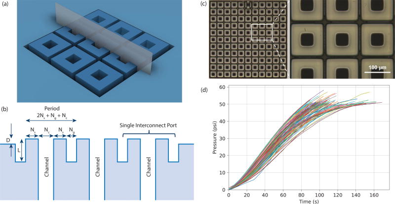
Fig. 6.
CCIM design. (a) Integrated microgaskets printed around each vertical channel in a square recess. (b) Schematic illustration of the cross section of the vertical plane in (a). The microgaskets have height D above the surrounding planar surface of the chip. (c) Composite image from four Zeta-20 microscope images of fabricated 11×11 array of CCIMs. Close up shows details of CCIMs. (d) Pressure as a function of time for the test set up in Fig. 5(a) repeated 100 times.

