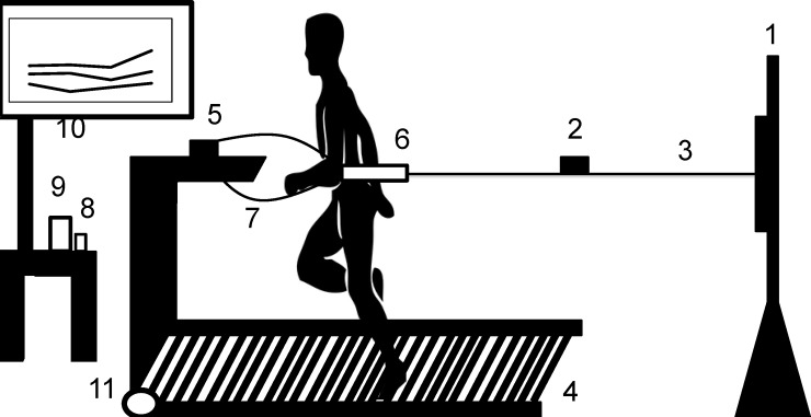
Fig 1. Schematic figure of the system developed on a non-motorized treadmill (NMT) for 3-min all-out (3MT) total power and critical power (CP) determination.
1. Height adjustment bar; 2. load cell; 3. steel cable with elastic cords (CP) or just steel cable (3MT); 4. NMT; 5. exhaustion apparatus; 6. belt attached to the steel cable and participant; 7. exhaustion apparatus security belt; 8. data acquisition module (DAC system); 9. signal amplifier; 10. computer; 11. hall effect sensor located on the treadmill’s front cylinder to determine the velocity that results from the connection with the DAC system.

