. 2018 Jan 11;7:e31522. doi: 10.7554/eLife.31522

Figure 5. Interface between the MukB neck and the MukF four-helix bundle.

(A) Left panel; cartoon of MukF N-terminal domain fragment carrying the N-terminal dimerisation domain (green) and part of the middle region (orange). Helices 8 and 9 are indicated in cyan. The mutated amino acid residues in variants FN2m1, FN2m2 and FN2m3 are indicated in yellow, red and purple, respectively, (residue R279 was altered in both m1 and m2, but is shown only in m2); views of helices 8 and 9 from different angles are shown separately. Right panel; ATPase activities of the mutated variants; means of initial rate measurements from three experiments are tabulated below. (B) Left panel; ATPase activities in the presence of MukF, of MukB and MukB variants mutated at the neck, MukBm1, blue, and MukBm3, yellow. Averages of initial rates from three experiments are tabulated underneath. Right panel; monomer of the MukB head (pdb 3EUK, Woo et al., 2009); the helix that emerges from the C-terminal subdomain of the head (C-ter helix) and forms the head-adjacent segment of the coiled-coil has been extended by modelling (shown in lilac). Right; enlarged view of the C-ter neck helix from the top with mutated residues shown. (C) Interactions of kleisin N-terminal domains with SMC necks. Left panel; Smc3-Scc1N; Gligoris et al. (2014). Right panel; B. subtilis SMC-ScpAN; Bürmann et al. (2013). The coiled-coil neck consists of two helical regions protruding from the SMC N-terminal head subdomain (N-ter helix; yellow), and from the C-terminal head subdomain (C-ter helix; red). Kleisin helices are shown in cyan.

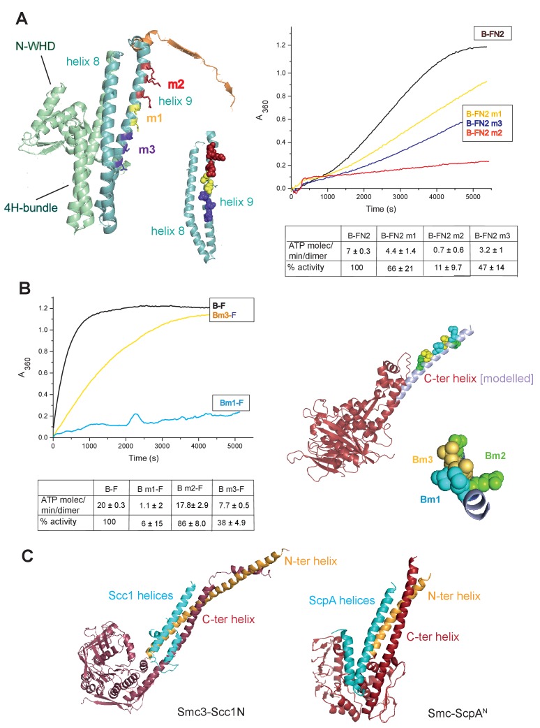
Figure 5—source data 1. Interface between the MukB neck and the MukF four-helix bundle.
DOI: 10.7554/eLife.31522.023

Figure 5.

Figure 5—figure supplement 1. Mutated FN2 fragments were defective in binding to MukBHN.

Figure 5—figure supplement 1.

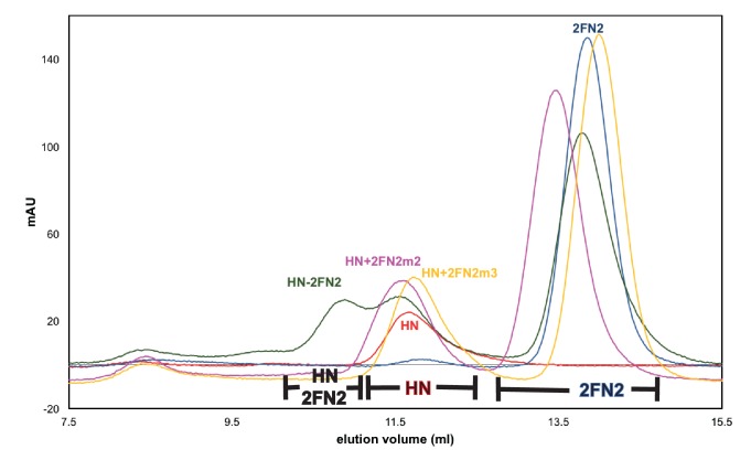
Binding of FN2 (dark grey trace), FN2m2 (R279E K283A R286A, pink trace), and FN2m3 (D261K S265K Q268A, yellow trace) to MukBHN was analysed by SEC on Sephadex 200 column using MukBHN (red trace) and FN2 (navy blue trace) as reference. The protein concentrations were: MukBHN - 3.7 μM (monomer) and FN2 variant - 4.6 μM (dimer). The ranges of elution volumes for HN-2FN2, HN and 2FN2 in various SEC runs are indicated below the traces.
Figure 5—figure supplement 2. Functional analysis of mutated MukF helix9 variants.

Figure 5—figure supplement 2.

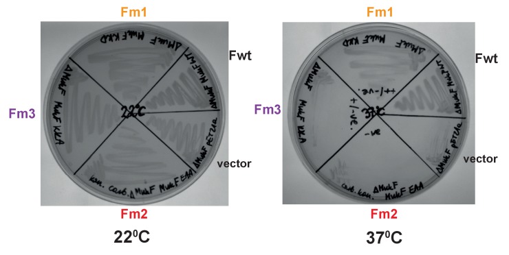
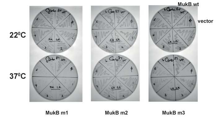
in vivo complementation in strain lacking chromosomal mukF gene by variants expressed from pET21 was assessed in the absence of IPTG (constitutive leaky expression). Growth material from colonies of each variant and MukF was streaked on LB and incubated at permissive, 22°C, and non-permissive, 37°C temperature and compared to negative control, empty vector.
Figure 5—figure supplement 3. Stimulation of the MukB neck variants, MukBm1 and MukBm3, ATPase by MukF, FN2 and FC2.

Figure 5—figure supplement 3.

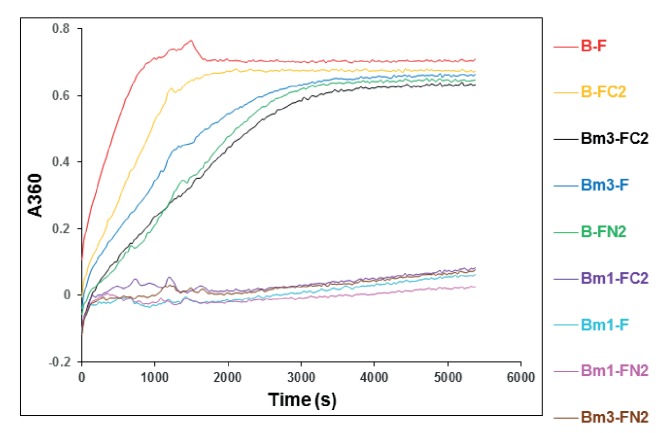
ATPase activity was measured at concentrations of MukB variant, 0.5 μM; MukF/FN2/FC2, 1.25 μM. The traces represent a single experiment.
Figure 5—figure supplement 3—source data 1. Stimulation of the MukB neck variants, MukBm1 and MukBm3, ATPase by MukF, FN2 and FC2.
DOI: 10.7554/eLife.31522.018
Figure 5—figure supplement 4. MukBm1 and MukBm3 fail to bind MukF N-terminal fragment.

Figure 5—figure supplement 4.

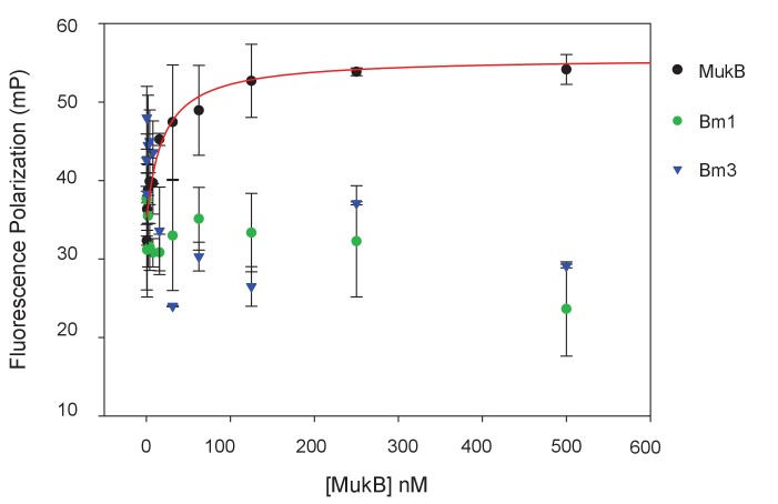
Binding of Cy5-labelled FN3 (at concentration of 5 nM) was assessed by FPA.
Figure 5—figure supplement 4—source data 1. MukBm1 and MukBm3 fail to bind MukF N-terminal fragment.
DOI: 10.7554/eLife.31522.020
Figure 5—figure supplement 5. Functional analysis of mutated MukB neck variants.

Figure 5—figure supplement 5.

in vivo complementation in cells lacking chromosomal mukB gene by variants expressed from pET21 plasmid. Growth of material streaked from 6 colonies of each variant was compared to growth of cells carrying WT MukB construct at permissive, 22°C, and non-permissive, 37°C; ϕ - a negative control, empty vector.
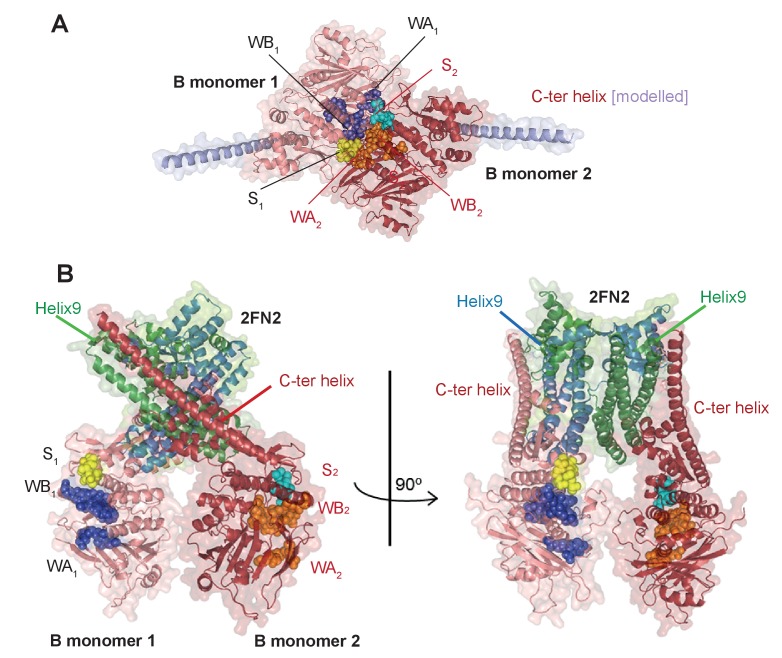
Figure 5—figure supplement 6. Model of the complex made by FN2 dimer binding two monomers of MukBHN.

Figure 5—figure supplement 6.

(A) Pymol cartoon of MukBHN complex based on the asymmetric complex structure from Woo et al. (2009), as shown in Figure 1B, but viewed from the top. ‘B monomer 1’, is coloured salmon pink, ‘B monomer 2’, intense red. The residues that make the motifs of ATPase catalytic binding sites are shown as spheres and indicated as follows: in monomer 1, Walker A and Walker B are coloured blue and signature loop in yellow; while in monomer 2, Walker A and Walker B are orange and the signature loop is in cyan; the modelled C-ter helices of the necks are shown in lilac. In this conformation, two assembled active sites, WA1 + WB1 + S2 and WA2 + WB2 + S1, bind two nucleotide molecules (not shown here). (B) A model of the MukBHN-2FN2-MukBHN complex inferred from the studies presented here shown in two views; the model assumes that FN2 dimer retains the conformation as seen in MukFE complex in the absence of MukB (Woo et al., 2009). Interactions between the two independently bound MukBHN necks and the helices of four-helix bundle of MukF N-terminal domain impose a conformation, in which the heads are turned around with respect to one another separating the catalytic active sites motifs.