Fig. 2.
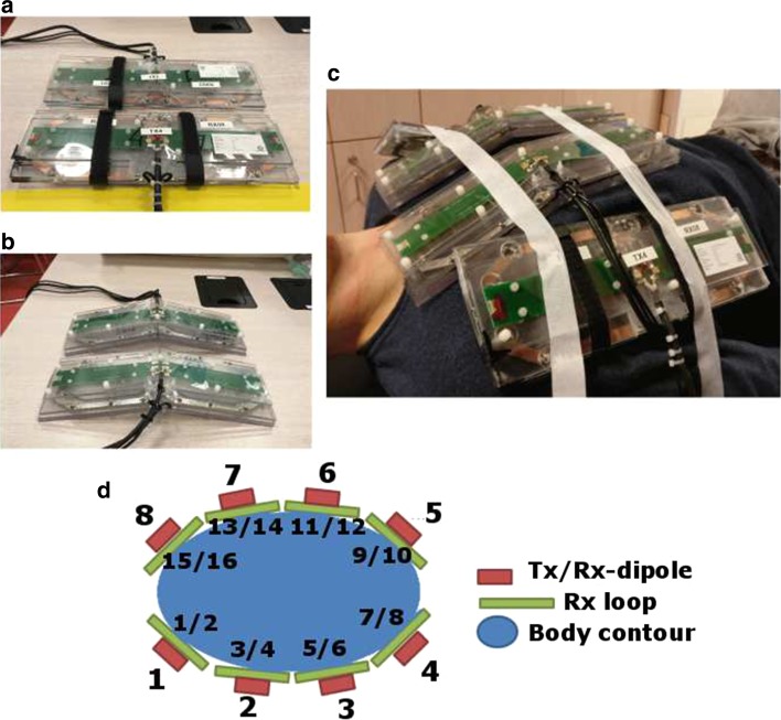
Schematic overview of the imaging setup. a Shows two elements consisting of a Tx/Rx antenna and two Rx loops. b Shows the two elements that are adapted to fit on the chest. c Shows a schematic drawing of the setup on a torso model. d Shows the transmit setup on a male volunteer. e Shows a noise covariance matrix on an exemplary volunteer

