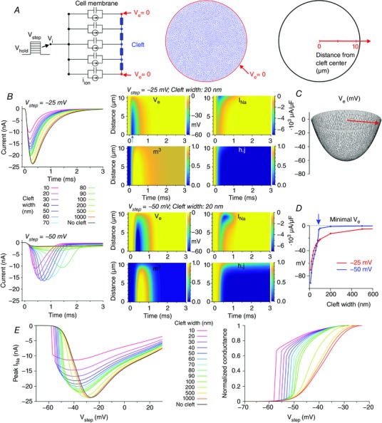
Figure 1. Dynamic interactions between I Na and V e in a disc‐shaped membrane (R disc = 11 μm) separated from a non‐conducting obstacle by an extracellular cleft (uniform distribution of g Na, Fg Na = 10.09).

A, schematic representation of the model (left: cross‐section; middle: finite element mesh) with membrane capacitance, ion currents and extracellular resistive properties (blue). V e at the rim of the disc was held at 0 (red). Due to radial symmetry (uniform Na+ channel distribution), the model behaviour does not depend on the azimuthal coordinate but only on the radial coordinate (right). B, left: total I Na during an activation step from −85 mV to −25 mV (top) and to −50 mV (bottom), for various cleft widths. B, middle: corresponding colour maps of V e, I Na, m 3 and hj as a function of time and distance from the centre, for a 20‐nm‐wide cleft. C, spatial profile of V e at the occurrence of the minimum (arrow in the middle panel of A) for V step = −25 mV and a cleft width of 20 nm. D, minimal V e registered in the cleft as a function of cleft width, for V step = −25 mV and −50 mV. Note the abrupt behaviour for V step = −50 mV (blue arrow). E, relationship between peak total I Na and V step for various cleft widths (left) and derived steady‐state activation curves (right).
