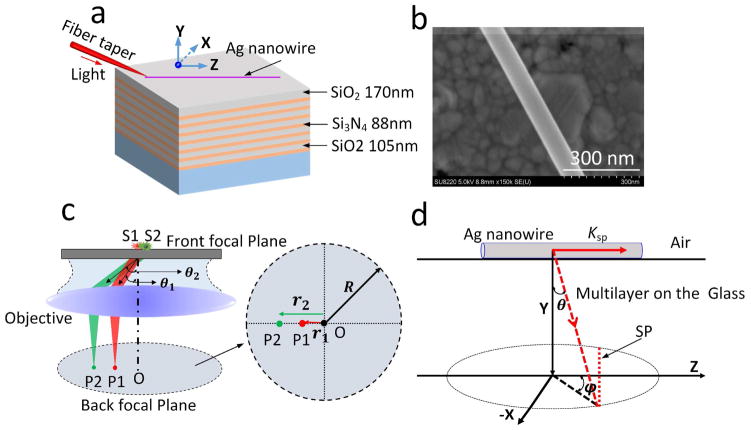
Figure 1. Schematic illustration of the experiment.
(a) An Ag NW was placed on a dielectric multilayer consisting of alternating layers of SiO2 (105-nm-thick) and Si3N4 (88-nm-thick). There were fourteen layers in total, with a top SiO2 layer with a thickness of 170 nm. A fibre taper was used to couple the laser beam into the nanowire. (b) SEM image of an Ag NW (diameter of 90 nm). (c) Illustration of the formation of BFP image. S1 and S2 denote the point emitters which is put on a glass substrate (the front focal plane of the objective). Their emitting angles are defined as ϑ1 and ϑ2, then two spots (P1 and P2) appear on the BFP, with distance to the centre spot O as r1 and r2, respectively. (d) Illustration of the BFP imaging formation for the plasmonic leaky mode propagating along an Ag NW. The plasmons with wave-vector (Ksp) propagate along the NW and leakage radiate simultaneously into the substrate with the angle at (ϑ and φ). Based on the momentum matching condition, this mode will be represented as a line (red dashed line lab led with SP) on the BFP image.

