
Figure 4.
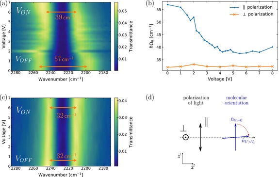
a, c) Transmittance map of a filled cavity with respect to the voltage applied for parallel and perpendicular polarization, respectively. b) Rabi‐splitting as a function of applied voltage over the cavity monitoring with the polarizer parallel (blue) or perpendicular (orange) to the alignment layer. d) Side view of the cell, where the polarization direction of the light can be compared to the molecular orientation with or without an applied voltage.