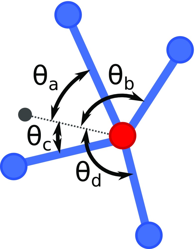
Fig. 1.
Schematic describing how angular restraints are applied for the node shown in red. A director, shown in gray, is attached to each node with a harmonic bond potential. Harmonic angles potentials are added between each pair of bonded nodes and the director, as indicated by the angles . The director is positioned such that are as far from 0° and 180° as possible. This scheme is applied at each node.

