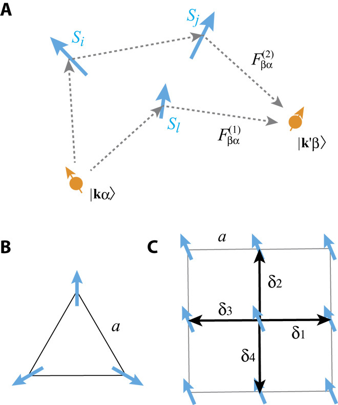
Fig. 1. Configuration of spins and skew scattering.

(A) Schematic picture of the scattering process in the second Born approximation in Eq. 5, which contributes to the skew scattering. The blue arrows are the localized spins, and the dotted lines and , indicate scattering processes from the first- and second-order terms in the Born approximation, respectively. The skew scattering arises from the interference between the two processes. (B) A schematic figure of the triangular configuration of spins considered in the main text. (C) The square lattice model considered in MC simulation. The arrows show δi vectors in Eq. 20, where a is the lattice constant (distance between the localized moments).
