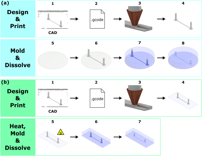
Figure 1.
(a) Fabrication procedure of high pressure PDMS flow chambers. (1–2) We design a customized channel scaffold using Autodesk Inventor Professional 2017 and translate the scaffold design into G-code using a slicing software. (3–4) We print the channel scaffold using a 3D printer using a water-soluble printing filament. (5–6) After curing a thin layer of PDMS on the bottom of a petri dish, we transfer and center the printed channel scaffold on the former using a pair of tweezers. (7–8) To finish the molding procedure, we pour and cure a second layer of PDMS on top of the scaffold. To dissolve the channel scaffold, we sonicate the flow chamber in a water bath. (b) Fabrication procedure of PDMS flow channels on a coverslip. Fabrication step 1–2 is identical to the procedure above. However, in (3–4) we now print the channel scaffold directly on a coverslip. To remove shape irregularities in channel shape, (5) we heat the printout on the coverslip on a hot plate. (6–7) To embed the channel scaffold, we clamp the printed coverslip in a custom-made molding device and add PDMS on top. After curing, we remove the coverslip/scaffold/PDMS assembly from the molding device and dissolve the channel scaffold in an ultrasonic water bath.

