Figure 3.
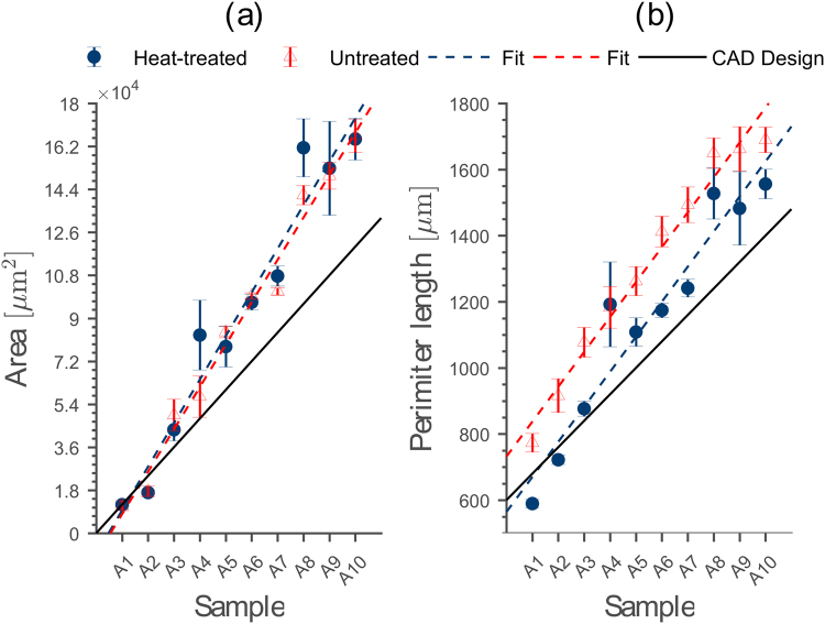
Comparison between printed channel scaffolds with different cross-sectional areas and perimeter lengths and their CAD design. (a) The median cross-sectional area A of both channel scaffolds show a linear increase with equal slope (untreated: R2 = 0.96, heat-treated: R2 = 0.91) with growing channel size. However, both overestimate the cross-sectional area of the CAD design for larger channels. (b) Median perimeter length Lp for the samples from (a). Again, untreated (R2 = 0.97) and heat-treated (R2 = 0.98) channel scaffolds show a linear increase for different sample sizes. Due to their regular surface, the median perimeter length of the heat-treated channels reproduces the CAD design better than the untreated channel scaffolds. The error bars represent the 95% confidence interval determined from 10 slices each for the 20 individual samples.

