Abstract
Purpose
This study demonstrates a novel PROPELLER (periodically rotated overlapping parallel lines with enhanced reconstruction) pulse sequence – Steer-PROP, based on gradient and spin echo (GRASE), to reduce the imaging times and address phase errors inherent to GRASE. The study also illustrates the feasibility of using Steer-PROP as an alternative to single-shot echo planar imaging (SS-EPI) to produce distortion-free diffusion images in all imaging planes.
Methods
Steer-PROP uses a series of blip gradient pulses to produce N (N = 3–5) adjacent k-space blades in each TR, where N is the number of gradient echoes in a GRASE sequence. This sampling strategy enables a phase correction algorithm to systematically address the GRASE phase errors as well as the motion-induced phase inconsistency. Steer-PROP was evaluated on phantoms and healthy human subjects at both 1.5T and 3.0T for T2- and diffusion-weighted imaging.
Results
Steer-PROP produced similar image quality as conventional PROPELLER based on fast spin echo (FSE), while taking only a fraction (e.g., 1/3) of the scan time. The robustness against motion in Steer-PROP was comparable to that of FSE-based PROPELLER. Using Steer-PROP, high quality and distortion-free diffusion images were obtained from human subjects in all imaging planes, demonstrating a considerable advantage over SS-EPI.
Conclusion
The proposed Steer-PROP sequence can substantially reduce the scan times as compared to FSE-based PROPELLER while achieving an adequate image quality. The novel k-space sampling strategy in Steer-PROP not only enables an integrated phase correction method that addresses various sources of phase errors, but also minimizes the echo spacing as compared to alternative sampling strategies. Steer-PROP can also be a viable alternative to SS-EPI to decrease image distortion in all imaging planes.
Keywords: GRASE, PROPELLER, Steer-PROP, phase correction, diffusion imaging, k-space trajectory
Introduction
Periodically rotated overlapping parallel lines with enhanced reconstruction (PROPELLER)1 is a rapid MRI method that traverses k-space using a series of rectangular strips, or “blades”, rotated about the k-space origin. Because the central region of k-space is sampled by every blade, PROPELLER allows for self-navigation, leading to excellent robustness against motion. As such, PROPELLER has been increasingly used clinically, particularly in T2-weighted imaging, diffusion imaging, FLAIR, and T2-mapping2–4.
The PROPELLER technique was initially implemented in a multi-shot fast spin echo (FSE) pulse sequence1,2. In that implementation, each spin-echo train within a TR produces a blade consisting of M parallel k-space lines, where M is determined by the echo train length (ETL)1,2. Subsequent repetitions (or TRs) involve a rotation of frequency- and phase-encoding gradients about the slice-selection axis, producing additional blades in k-space. FSE-based PROPELLER (FSE-PROPELLER) inherits many desirable properties of FSE, especially the high-resolution capability and the excellent immunity to off-resonance effects due to the use of multiple refocusing radiofrequency (RF) pulses. Compared to other fast imaging techniques5, sequences based on FSE may not offer adequate data acquisition efficiency in some demanding applications, such as diffusion imaging with multiple b-values and/or a large number of gradient directions6–8. Additionally, the large number of RF pulses in FSE-PROPELLER can escalate the specific absorption rate (SAR), especially at high magnetic fields.
PROPELLER sequences based on echo planar imaging (EPI), including long-axis PROPELLER (LAP)9 and short-axis PROPELLER (SAP)10, were introduced to address the aforementioned problems by acquiring each blade using an echo-planar readout. EPI allows more efficient k-space sampling than FSE, resulting in wider blades to improve motion correction and fewer blades to cover k-space while mitigating the SAR concerns9. However, EPI is very sensitive to off-resonance effects, producing artifacts such as image distortion5. Although the problem can be less in SAP than in LAP, the sensitivity to off-resonance, in general, remains as a significant challenge.
Gradient and spin echo, or GRASE11, is a sequence that can combine the merits of FSE and EPI and provide a compromise of their pitfalls. In Turboprop proposed by Pipe and Zwart12, a PROPELLER sequence is implemented in GRASE by incorporating a short gradient-echo train (e.g., ETL = 3–7) into each spin echo in an FSE echo train. This widens the blade and consequently improves the robustness of motion correction. Additionally, Turboprop increases the data acquisition efficiency without escalating the SAR by using fewer blades to sample entire k-space. Like other GRASE sequences5, Turboprop faces the challenges of phase correction within each blade. The intra-blade phase errors can become complicated because of the two inter-tangled sources: phase errors arising from violation of the Carr-Purcell-Meiboom-Gill (CPMG) conditions (i.e., FSE-type phase error) and phase errors due to the EPI-type k-space traversal (i.e., EPI-type phase error). To untangle these phase errors, another GRASE-based PROPELLER sequence, X-PROP13, was proposed by assigning the gradient echoes into individual blades. Because each blade does not contain a mixture of gradient echoes, phase correction can be simplified and readily incorporated into PROPELLER reconstruction1. However, X-PROP spreads the multiple blades from a gradient-echo train evenly across k-space, necessitating a relatively large gradient area in-between the gradient echoes, which lengthens echo spacing. Additionally, X-PROP has been implemented with a split-blade technique to address the CPMG conditions12,13, which halves the blade width and compromises motion correction.
Stimulated by prior work, we report an alternative GRASE-based PROPELLER technique, which we call Steer-PROP. Unlike Turboprop, Steer-PROP uses a series of blip gradient pulses to produce multiple blades in one shot (or TR). Unlike X-PROP, Steer-PROP can minimize the echo spacing for both gradient-echo and spin-echo trains. We demonstrate that Steer-PROP is capable of reducing the scan time by a factor of at least three as compared to FSE-PROPELLER and producing distortion-free images in all imaging planes, making the technique a viable alternative to conventional single-shot EPI (SS-EPI) sequence for diffusion imaging.
Methods
Pulse Sequence Design
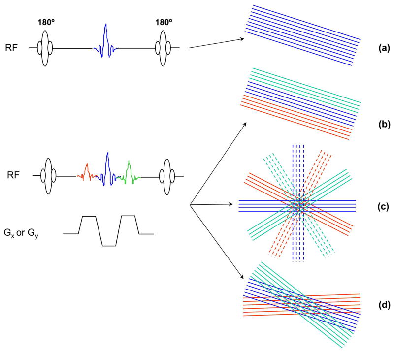
Steer-PROP uses M (e.g., M = 8–16) refocusing RF pulses after each excitation RF pulse to produce a CPMG spin-echo train. As in Turboprop12, each spin echo is further split into N (e.g., N = 3–5) gradient echoes using a bipolar readout gradient. Unlike Turboprop12 where the multiple gradient echoes within a spin echo are used to sample a total of M×N parallel k-space lines all within the same blade, Steer-PROP employs a series of blip gradient pulses to distribute the N gradient echoes to N different blades. In doing so, N blades, each containing M lines, are sampled following each RF excitation (or TR). Unlike X-PROP13, which produces 2N blades (each with M/2 k-space lines) and distributes them evenly over a π range in k-space, Steer-PROP arranges the N blades adjacent to each other over a limited angular range in k-space. In addition, X-PROP splits the odd and even spin echoes between two orthogonal blades13. In contrast, Steer-PROP combines the odd and even spin echoes in the same blade by placing the even echoes at the central region of a blade and the odd echoes at the edges to minimize artifacts, as proposed previously14. The difference in k-space coverage among FSE-PROPELLER, Turboprop, X-PROP, and Steer-PROP is shown in Fig. 1. To use Steer-PROP for diffusion imaging, diffusion gradients are introduced to either side of the first refocusing RF pulse (Fig. 2a), similar to an earlier FSE-PROPELLER implementation2.
Figure 1.
Different k-space sampling strategies in FSE-PROPELLER (a), Turboprop (b), X-PROP (c), and Steer-PROP (d). Only a segment of the pulse sequence between two consecutive refocusing RF pulses is shown. In FSE-PROPELLER (a), each spin echo is used to sample a k-space line in a blade. All spin echoes in a TR are used to sample a single PROPELLER blade. In Turboprop (b), X-PROP (c), and Steer-Prop (d), each spin echo is split into three gradient echoes. Turboprop uses all three gradient echoes to sample the same widened PROPELLER blade. X-PROP assigns the odd (solid lines) and even spin echoes (dash lines) into orthogonal blades and distributes all six blades evenly over an angular range of π, whereas Steer-PROP distributes the three gradient echoes to adjacent blades with a narrow angular range.
Figure 2.
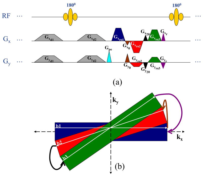
(a): A segment of a Steer-PROP sequence illustrating steering gradient design for the special case of N = 3. (b): k-Space trajectory of the sequence segment in (a). Gx and Gy are used to denote readout (or X) and phase-encoding (or Y) gradients in a conventional sequence. Gxd1, Gxd2, Gyd1 and Gyd2 are the diffusion gradients on the X and Y axes as indicated. Gpe is a phase-encoding pulse for the spin echo, Gxro1 is the readout gradient pulse corresponding to the 1st gradient echo, Gxro2 and Gyro2 are the X and Y components corresponding to the 2nd gradient echo, Gxro3 and Gyro3 are the X and Y components corresponding to the 3rd gradient echo, Gxθ, Gyθ, Gx2θ, and Gy2θ are the steering gradient pulses, and Gxr and Gyr are the phase-rewinding pulses. The three k-space lines sampled by the three gradient echoes are illustrated as the white lines (denoted as b1, b2, and b3, respectively) in their respective color-coded blades. The curved arrow lines illustrate the effect of the steering gradient pulses or the rewinding gradient pulse on the k-space trajectory with the color of the lines corresponding to the same color of the gradient pulses in (a).
Steering Gradient Design
The mechanism for steering between blades within a gradient-echo train is illustrated in Fig. 2a which shows a single spin-echo segment of the Steer-PROP sequence with an optional diffusion gradient pair. The cyan phase-encoding gradient provides a phase offset to assign a specific position of a k-space line within a blade. The blue, red, and green readout gradient lobes correspond to different k-space lines in different blades acquired by different gradient echoes within the spin echo. The brown and black gradient pulses are termed as steering blips, or steering gradients, that are used to steer the k-space trajectory to the adjacent blade. The purple gradient pulses at the end of the gradient-echo train rewind the phase along the ky - and kx -directions in order to satisfy the CPMG conditions for T2-weighted imaging. Rewinding the phase also helps meeting the CPMG conditions later in the echo train after the first refocusing pulse interval when a diffusion-weighting gradient is applied. The detailed k-space trajectories are shown in Fig. 2b where the three k-space lines sampled by the three gradient echoes are illustrated as the white lines (denoted as b1, b2, and b3, respectively) in their respective color-coded blades. The curved arrow lines illustrate the effect of the steering or rewinding gradient pulses on the k-space trajectory with the color of the lines corresponding to the color in Fig. 2a.
The segment in Fig. 2a is repeated M times throughout the spin-echo train, producing the remaining k-space lines for each of the N blades. With this sampling scheme, each excitation (or TR) acquires a total of M×N k-space lines that are evenly distributed among the N blades, improving the data acquisition speed by a factor of N as compared to FSE-PROPELLER with the same spin echo train length. For a desired reconstruction matrix size, L, the minimal number of excitations, P, to cover k-space is calculated by1
| [1] |
In order to achieve the k-space traversal shown in Fig. 2b, the areas of individual steering blip pulses were determined as shown in Fig. 3. These steering pulse areas depend on the phase-encoding amplitude of the spin echo under consideration and the rotation angle (θ) between two adjacent blades. For a specific k-space line to be steered, the area (Ay) of its corresponding phase-encoding gradient is given by Eq. [2], and the area corresponding to the largest phase-encoding step within a blade (Aymax) is given by Eq. [3]:
| [2] |
| [3] |
where FOV is the field of view in units of cm, γ is the gyromagnetic ratio (i.e., 4.258 kHz/Gauss for protons), φ is the phase-encoding index in the blade within the range of −E + 1 ≤ φ ≤ E, and E corresponds to the largest positive phase-encoding step within the blade and is given by E = M/2.
Figure 3.
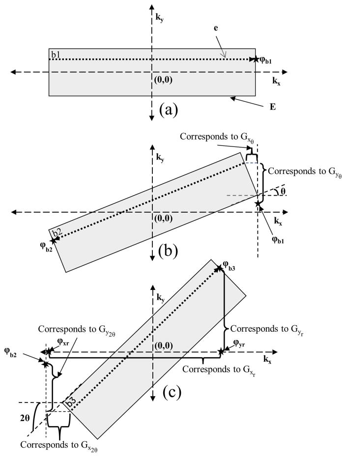
Steering gradient design using a gradient-echo train of 3 (N = 3). k-Space lines sampled by the three gradient echoes are denoted as b1, b2, and b3 in (a), (b), and (c), respectively. θ is the angle between two subsequent blades. φb1, φb2 and φb3 are the ending locations of k-space lines b1, b2, and b3, respectively. Gxθ, Gyθ, Gx2θ, and Gy2θ are the steering gradients as explained in the text. Rewinding gradient pulses (Gxr and Gyr ) return the k-space trajectory to the kx -axis as if steering had not happened. The Gyr rewinding pulse performs k-space traversal from point φb3 to its projection on the kx -axis (φyr) and the Gxr rewinding pulse performs k-space traversal from φyr to the starting location in the first blade (φxr).
The blip gradient pulse area required to steer from one blade to the adjacent blade was calculated by distributing Ay and Aymax into their corresponding readout and phase-encoding directions. Figure 3 employs a case of N = 3 as an example to demonstrate the design of steering gradient pulses. The blade in Fig. 3a is a horizontal blade in parallel to the kx-axis. The subsequent two adjacent blades are rotated with an angle of θ and 2θ, respectively. The phase-encoding gradient (cyan in Fig. 2a) at the beginning of the gradient-echo train determines the initial position of k-space line b1 in the first blade (Fig. 3a). After the acquisition of this k-space line, the steering gradient pulses Gxθ and Gyθ advance the k-space point labeled with an asterisk (i.e., point φb1) to a new starting position in the second blade (Fig. 3b). Conceptually, this k-space transition comprises two components: (a) moving from point φb1 upward with a Gyθ gradient, and (b) moving horizontally with a Gxθ gradient to the corresponding initial location in the second blade for acquiring k-space line b2. The gradient areas required for these two orthogonal components are given by Eqs. [4] and [5] in the Appendix. To advance from the second to the third blade, a similar strategy was used with the blip gradient areas Ay2θ (for Gy2θ) and Ax2θ (for Gx2θ) as shown in the Appendix.
Once the areas for all steering gradients are determined, the corresponding gradient pulses can be designed by minimizing the pulse width within the slew-rate and gradient amplitude constraints as shown in a reference5. It is worth noting that the gradients Gxθ and Gy2θ in Figs. 3b and 3c have negative polarity as required by their traversal direction. Although we use a special case of N = 3 to illustrate the steering pulse design, the same principles can be extended to other gradient echo train lengths. Once the steering gradient pulses are designed, the ending position point φb3 of the b3 k-space line (Fig. 3c) is tracked, followed by a pair of rewinding gradient pulses (purple pulses Gxr and Gyr in Fig. 2a) to return the k-space trajectory to the kx-axis as if steering had not happened (i.e., as if a conventional Cartesian GRASE sequence were used). The areas of the rewinding gradients are provided in the Appendix (Eqs. [8] and [9]).
Once a set of steering and rewinding gradient pulses is designed for the first spin echo, the gradient pulses for the subsequent spin echoes can be designed analogously with different initial k-space lines. To generate the remaining sets of N blades in subsequent TRs, the rotation matrix of the scanner was employed with a rotation angle increment of 3θ (or Nθ) per TR without the need of designing additional steering and rewinding gradients.
Phase Corrections
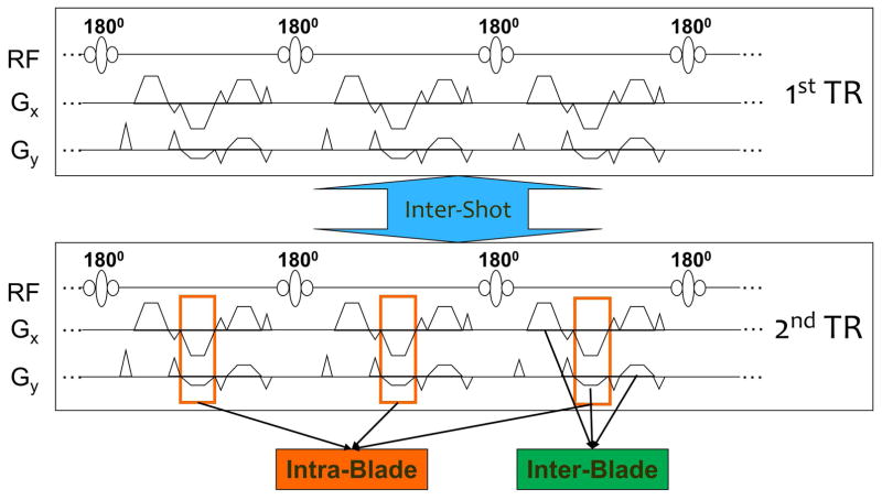
The Steer-PROP sequence is subject to three types of phase errors that must be accounted for in order to ensure image quality. A segment of the sequence consisting of two subsequent TRs (or shots) is shown in Fig. 4 where the different phase errors are illustrated.
Figure 4.
A segment of Steer-PROP consisting of two repetition times (TRs or shots) denoted as 1st TR and 2nd TR. Three kinds of phase errors are shown: intra-blade (k-space lines within a single blade acquired by different spin echoes in the same echo train), inter-blade (among the blades acquired by the gradient echoes within a single spin echo), and inter-shot (between TRs) phase errors. Note that although the refocuses pulses are labeled as 180°, the actual flip angle was adjusted between 160° and 180° to stabilize the echo amplitudes in the spin-echo train.
The k-space lines within a blade are acquired from different spin echoes, subject to FSE-type phase errors. We call this type of phase error as intra-blade phase error (Fig. 4). The intra-blade phase error can be estimated by using two additional spin echoes in the echo train (i.e., M′ = M+2) that are not phase-encoded5,15,16. The constant and linear phase errors obtained from the non-phase-encoded echoes are then used for phase correction.
Similar to EPI, the gradient echoes within a gradient-echo train can have inconsistent phase errors, or EPI-type phase errors, that lead to phase inconsistency among the blades acquired within the same shot. We call this phase error as inter-blade phase error (Fig. 4). Because all blades acquired within a shot intersect at the k-space central region, the data redundancy can be exploited for phase correction analogously to in-plane motion phase correction in PROPELLER1.
Motion also induces phase errors between TRs or shots. We refer this phase error to as inter-shot phase error (Fig. 4). The central overlapping region of k-space can be used to perform both inter-blade and inter-shot phase error corrections during image reconstruction using the method proposed by Pipe1.
Pulse Sequence Implementation
The Steer-PROP sequence was implemented and evaluated on two General Electric MRI scanners operating at 1.5T (Signa HDx) and 3.0T (Signa HDxt), respectively. A commercial FSE pulse sequence was modified to implement the Steer-PROP pulse sequence detailed in the Methods section. All images were reconstructed, with corrections for intra-blade, inter-blade, and inter-shot phase errors, using custom C++ and MATLAB programs.
Experimental Studies
To demonstrate and evaluate the performance of Steer-PROP, four experiments were conducted. In the first experiment, the pulse sequence was tested on a cylindrical GE DQA phantom at 3.0T using a head coil. T2-weighted Steer-PROP images were acquired in the axial plane with the following parameters: TR = 4s, effective TE = 72ms (based on the definition of effective TE for GRASE), M = 8, N = 3, number of shots = 16, FOV = 24cm, slice thickness = 5mm, bandwidth (BW) = ±125 kHz, matrix size = 256×256, NEX = 2 (with phase-cycling to remove a DC offset), and scan time = 2 mins 9 secs. For comparison, a similar image was obtained using a conventional FSE-PROPELLER sequence with the same imaging parameters except for N = 1 and scan time = 6 mins 27 secs. To compare the performance between the Steer-PROP and the conventional FSE-PROPELLER, signal-to-noise (SNR) was calculated from the images in a uniform region (shown by the green and orange arrows in Fig. 5 for computing the signal and noise, respectively). The SNR was normalized with respect to the acquisition time (i.e., SNR/√time) to facilitate the comparison.
Figure 5.
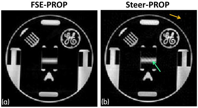
Comparison of phantom images obtained at 3.0T using (a) FSE-PROPELLER and (b) Steer-PROP pulse sequences. The acquisition parameters were TR = 4s, effective TE = 72ms, M = 8, N = 3 (for Steer-PROP), number of shots = 16, FOV = 24cm, slice thickness = 5mm, bandwidth (BW) = ±125 kHz, matrix size = 256×256, and NEX = 2. The scan times for the two images were 6 mins 27 secs in (a) and 2 mins 9 secs in (b). The green and orange arrows on the Steer-PROP image indicate regions where signal and noise were measured, respectively, for SNR calculations.
In the second experiment, the performance of the Steer-PROP sequence was illustrated on a 29-year old healthy female human subject for both T2- and diffusion-weighted imaging at 1.5T. Axial images were acquired with Steer-PROP and FSE-PROPELLER sequences using the following imaging parameters: TR = 4s, effective TE = 72ms, M = 8, N = 3 (for Steer-PROP), FOV = 24cm, slice thickness = 5mm, BW = ±62.5 kHz, matrix size = 256×256, NEX = 2, and scan time = 2 mins 9 secs for Steer-PROP and 6 mins 27 secs for FSE-PROPELLER. A narrower BW was used to partially compensate for the reduced SNR at 1.5T. For diffusion-weighted imaging, a b-value of 750 s/mm2 was used, and the diffusion-weighting gradient was applied along the right-left direction.
The third experiment was intended to assess the robustness of the Steer-PROP sequence to subject motion. A healthy female volunteer was instructed to move her head with low to moderate frequency randomly during the acquisition. Axial Steer-PROP and FSE-PROPELLER T2-weighted images were acquired from the brain at 3.0T with the following imaging parameters: TR = 4s, effective TE = 128ms (achieved by stretching the spin-echo spacing to match a clinical FSE-PROPELLER protocol for heavy T2-weighting), M = 8, N = 3 (for Steer-PROP), matrix size = 256×256, FOV = 26 cm, slice thickness = 5 mm, and NEX = 2. The immunity to motion artifacts using Steer-PROP versus FSE-PROPELLER was compared, together with a comparison with a standard multi-shot T2-weighted Cartesian FSE acquisition.
When imaging in non-axial planes, SS-EPI often suffers from substantial distortion due to orientation-dependent magnetic susceptibility effects and concomitant gradient fields17,18. The fourth experiment was designed to evaluate the flexibility in imaging planes with Steer-PROP for diffusion imaging. Brain images in axial and non-axial (i.e., sagittal, coronal, and oblique) planes were acquired from a volunteer at 3.0T using the following parameters: TR = 4s, effective TE = 72ms, M = 8, N = 3, FOV = 24cm, slice thickness = 5mm, BW = ±125 KHz, matrix size = 256×256, NEX = 2, b = 750 s/mm2, and scan time = 2 mins 13 secs. The oblique plane was chosen in parallel to the cerebellar tentorium, approximately 40° from the axial plane. For comparison, diffusion-weighted images using SS-EPI were also acquired in the same planes.
Results
Figure 5 shows two T2-weighted images of the phantom acquired at 3.0T. Steer-PROP (Fig. 5b) produced similar image quality as FSE-PROPELLER (Fig. 5a), while taking only one third of the scan time. Quantitative measurement of SNR revealed a ~30% reduction in the Steer-PROP image (SNR = 77) as compared to the FSE-PROPELLER image (SNR = 110). However, when the SNR was normalized with respect to the scan time, Steer-PROP yielded a higher normalized SNR (SNR/√time = 6.78 (√sec)−1) than the FSE-PROPELLER image (SNR/√time = 5.59 (√sec)−1). Other than minor streak artifacts in the central region, possibly caused by off-resonance sensitivity due to the magnetic susceptibility effects associated with the phantom geometry, the Steer-PROP image was free of other artifacts.
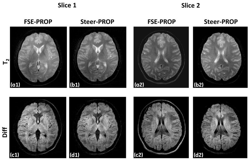
Figure 6 shows two slices comparing T2- and diffusion-weighted images at 1.5T. The Steer-PROP images (Figs. 6b1, 6d1, 6b2, and 6d2) display comparable image quality to that of the FSE-PROPELLER images (Figs. 6a1, 6c1, 6a2, and 6c2), despite a three-fold reduction in scan time (2 min 9 secs vs. 6 min 27 secs).
Figure 6.
Two slices of T2-weighted (a1, b1, a2, and b2) and diffusion-weighted (b = 750 s/mm2; c1, d1, c2, and d2) images from a human volunteer obtained at 1.5T using FSE-PROPELLER (first and third columns) and Steer-PROP (second and fourth columns) with TR = 4s, effective TE = 72ms, M = 8, N = 3 (for Steer-PROP), FOV = 24cm, slice thickness = 5mm, BW = ±62.5kHz, matrix size = 256×256, and NEX = 2.
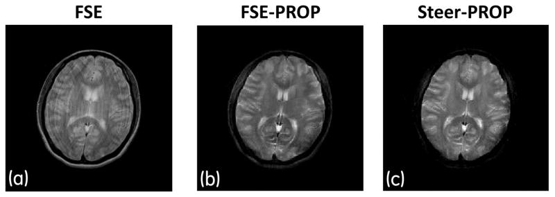
Images for demonstrating robustness against motion are shown in Fig. 7. While the conventional Cartesian FSE image (Fig. 7a) showed severe motion-related ghosting artifacts, both FSE-PROPELLER (Fig. 7b) and Steer-PROP (Fig. 7c) exhibited good immunity to motion artifacts and the performance of these two sequences was similar.
Figure 7.
T2-weighted images (TR = 4s, effective TE = 128ms, M = 8, N = 3 for Steer-PROP, matrix size = 256×256, FOV = 26cm, slice thickness = 5mm, and NEX = 2) of a healthy human volunteer obtained on a 3.0T scanner using (a) conventional Cartesian FSE, (b) FSE-PROPELLER, and (c) Steer-PROP. The subject’s head was moving randomly during all three scans.
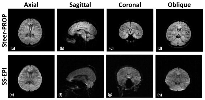
Lastly, diffusion-weighted images produced by the Steer-PROP sequence in all imaging planes (axial, sagittal, coronal, and oblique) are shown in the top row of Fig. 8. These images were compared with the corresponding images obtained with the conventional SS-EPI sequence (bottom row of Fig. 8). The axial images (Fig. 8a vs. Fig. 8e) showed the smallest discrepancies. For images acquired in the sagittal plane, the SS-EPI images (Fig. 8f) exhibited substantial gross distortion. The distortion was virtually eliminated in the corresponding Steer-PROP image (Fig. 8b). Similar improvements were also observed in coronal (Fig. 8c vs. Fig. 8g) and oblique (Fig. 8d vs. Fig. 8h) planes.
Figure 8.
Diffusion-weighted images (TR = 4s, effective TE = 72ms, M = 8, N = 3 for Steer-PROP, FOV = 24cm, slice thickness = 5mm, BW = ±125 KHz, matrix size = 256×256, NEX = 2, and b = 750 s/mm2) acquired on a 3.0T scanner using Steer-PROP (a–d) and SS-EPI (e–h) on axial (a, e), sagittal (b, f), coronal (c, g), and oblique (d, h) planes. The oblique slice orientation was selected to be in parallel to the cerebellar tentorium, ~ 40° from the axial plane. The sub-optimal image quality in (e) was a reflection of poor B0-field homogeneity. Even in the presence of B0-field homogeneity, a high quality Steer-PROP image in (a) was obtained.
Discussion
By combining GRASE and PROPELLER, we have demonstrated that Steer-PROP can accelerate the image acquisition in T2-weighted and diffusion-weighted imaging by a factor of 3 compared to PROPELLER sequences employing FSE. This combination has produced comparable image quality to that from FSE-PROPELLER at both 1.5T and 3.0T (Figs. 5 and 6).
In Cartesian sampling, it has long been recognized that GRASE can combine the merits of FSE (e.g., off-resonance insensitivity) and EPI (e.g., reduced SAR and rapid acquisition speed)11. These merits have been exploited in several GRASE-based PROPELLER sequences. In Turboprop (Fig. 1b), the multiple gradient echoes are combined in a single blade12. While this approach can substantially increase the width of the blade, allowing a more efficient motion correction and a shorter scan time, the EPI-type phase errors among the gradient-echoes must be corrected to ensure good image quality5. Such phase correction is not trivial as the FSE-type phase errors can be intermingled with the EPI-type phase-errors within the same blade. Untangling these phase errors typically requires acquisition of additional reference scans12 that compromises the overall data acquisition efficiency.
PROPELLER sampling strategy provides a natural way to de-tangle the EPI-type and FSE-type phase errors in a GRASE sequence. This was first demonstrated in a multi-echo GRASE-PROPELLER implementation in which the different gradient echoes within a spin echo were used to sample a set of blades, all with the same blade angle but different T2*-weighting19. Multi-echo images were obtained to either increase the SNR or produce a T2*-map. This concept was employed in the earlier implementations of Steer-PROP20 and X-PROP13 by distributing the N gradient echoes within a spin echo into separate blades, thereby allowing acquisition of multiple blades in each TR to accelerate data acquisition.
Although Steer-PROP and X-PROP share the similar concept, there are important differences. First, X-PROP was implemented using a split-blade approach that assigns the odd and even echoes of an FSE echo train into orthogonal blades, resulting in 2N blades from each TR with a blade width only half of that of Steer-PROP. While the split-blade approach is more robust with respect to the CPMG conditions, the narrowed blade width makes PROPELLER motion correction less effective. Even without using the split-blade approach, Steer-PROP has produced good image quality (Figs. 5–8), illustrating that artifacts arising from possible violation to the CPMG conditions are not severe. Second, X-PROP distributes multiple blades from a TR evenly in k-space over a range of π, which leads to a larger area of the steering gradient pulses. The increased gradient area in turn results in a longer echo spacing (for both gradient-echo and spin-echo trains). In contrast, Steer-PROP positions the multiple blades from the gradient echoes adjacent to each other over a limited angular range (Fig. 2). This strategy leads to the smallest steering gradient area and consequently minimizes echo spacing. The exact difference in echo spacing between Steer-PROP and X-PROP depends on the system hardware, k-space trajectory, and other acquisition parameters. As an example, Table 1 shows comparisons of echo spacing using the protocols in the first two experiments (Figs. 5 and 6) at 3.0T and 1.5T, respectively. Using Steer-PROP, a reduction in echo spacing up to 25.7% can be achieved for the gradient-echo train. Third, because of the difference in steering gradient amplitudes and/or duration, Steer-PROP produces less eddy currents than X-PROP. While the readout and crusher gradients (as well as diffusion gradients when applicable) can dominate eddy current production, eddy currents from the steering gradients may not be negligible, especially when the k-space blades are not adjacent to each other as in X-PROP. Such eddy currents can be particularly detrimental as the associated k-space correction has not been well developed. Lastly, X-PROP was demonstrated in a diffusion-weighted sequence with split blades, whereas Steer-PROP was implemented in a conventional PROPELLER sequence for both T2-weighted and diffusion-weighted imaging. Despite the differences, both Steer-PROP and X-PROP can successfully separate and effectively correct for the EPI-type and FSE-type phase errors in a GRASE sequence, as shown in Fig. 4 and references13,20. In this study, we have explicitly separated the three types of phase-errors: intra-blade phase error (i.e., FSE-type error), inter-blade phase error (i.e., EPI-type error), and inter-shot phase error (i.e., motion-induced error) and described the correction strategy.
Table 1.
Comparison of Echo Spacing between Steer-PROP and X-PROP
| Steer-PROP (ms) | X-PROP (ms) | |||
|---|---|---|---|---|
| Gradient-Echo | Spin-Echo(a) | Gradient-Echo | Spin-Echo(a) | |
| Experiment 1 (3.0 T) | 1.460 | 7.872 | 1.836 | 8.820 |
| Experiment 2 (1.5 T) | 2.332 | 10.520 | 2.600 | 11.256 |
The refocusing RF pulse width was 2.2ms, and the crusher gradient width was 0.7ms.
In the phantom study (Fig. 5), we quantitatively compared the SNR/√time between a commercial FSE-PROPELLER sequence and Steer-PROP and demonstrated a higher SNR efficiency with Steer-PROP. It is worth noting that such comparison is subject to a number of limitations. First, a relatively broad receiver BW (±125 kHz) was employed in the Steer-PROP sequence in order to achieve a short gradient-echo spacing. A narrow BW of ±62.5 kHz was also investigated. However, the SNR gain was inadequate to counterbalance the SNR loss and the exacerbated off-resonance effects due to lengthening of echo spacing at 3T. In practice, FSE-PROPELLER does not need such a broad BW. A fairer comparison would use a narrower BW in FSE-PROPELLER to match the readout duration of the gradient echo-train in Steer-PROP. Constrained by the inflexibility in continuously changing BW on the scanner, we did not perform such comparison. Second, the total sequence length of Steer-PROP was longer than that of FSE-PROPELLER. In principal, additional spin echoes (i.e., more lines in a blade) can be acquired by FSE-PROPELLER with an equivalent sequence length to that of Steer-PROP, leading to a higher SNR/√time for FSE-PROPELLER. Finally, the SNR should be normalized with respect to not only acquisition time but also the number of slices per TR, which is determined jointly by sequence length and SAR. In this study, the SAR in Steer-PROP was lower than that in FSE-PROPELLER because identical refocusing RF pulses were used in both sequences, but FSE-PROPELLER had a shorter spin-echo spacing with more densely packed RF pulses. We did not attempt to optimize SAR for Steer-PROP in this study or normalize the SNR with respect to the number of slices, which can be important areas for future studies.
Compared to SS-EPI that has been used extensively in diffusion imaging, Steer-PROP can substantially reduce the image distortion arising from off resonance, as illustrated in Fig. 8. The benefit from the Steer-PROP sequence on non-axial images is significantly more evident. The ability of obtaining high quality diffusion images in non-axial planes is particularly important, as this has been a substantial limitation with SS-EPI which is sensitive to susceptibility differences and concomitant fields17. The benefit of using Steer-PROP is expected to be even greater at a lower magnetic field (e.g., ≤1.5T) where the problems caused by concomitant fields are more pronounced17,18 and the T2* value is longer.
In this study, the in vivo demonstration was limited to the brain where the relatively long T2 and T2* values facilitate application of Steer-PROP. The same sequence can also be applied to other organs with a proper adjustment of M and N to be consistent with the T2 and T2* values of the tissues of interest. Our experimental demonstration typically employed three gradient echoes (N = 3), although a longer gradient-echo train (e.g., N = 5) may also be used provided that the T2*-induced signal decay is moderate. With a larger N, the spin-echo train length (M) needs to be shortened accordingly to keep the entire sequence length within the signal decay window imposed by the T2 relaxation.
Although we focused primarily on T2- and diffusion-weighted imaging in the experimental studies, the Steer-PROP sequence can be generalized to produce other contrasts, such as T1 and proton density contrast. Additionally, the sequence may also be combined with other sequence modules such as magnetization transfer, flow compensation, and spin tagging.
Conclusion
We have demonstrated that the proposed Steer-PROP sequence can considerably reduce the scan time as compared to commercial FSE-PROPELLER sequences while achieving an adequate image quality. Additionally, the novel k-space sampling strategy employed in Steer-PROP not only enables an integrated phase correction strategy that systematically addresses several types of phase errors, but also minimizes the echo spacing as compared to alternative sampling strategies. Steer-PROP can also be a viable alternative to SS-EPI to decrease the image distortion and improve the spatial resolution in all imaging planes.
Acknowledgments
This work was supported in part by a grant from the National Institute of Health (Grant No. 1S10RR028898). The authors are grateful to Drs. Aziz Poonawalla, Keith R. Thulborn, Yi Sui, and Muge Karaman for helpful discussions, and Michael Flannery and Hagai Ganin for technical assistance.
Appendix
For the first pair of steering gradient pulses Gxθ and Gyθ shown in Fig. 2a, their gradient areas are given below:
| [4] |
| [5] |
These gradient areas advance the k-space position at the end of the first blade acquisition (i.e., point φb1 in Fig. 3) to a new starting position in the second blade.
Similarly, to advance the k-space position from the second to the third blade, the steering gradient areas for Gx2θ and Gy2θ are given by
| [6] |
| [7] |
At the end of the acquisition of the third blade, the areas of the rewinding gradients Gxr and Gyr are determined by
| [8] |
| [9] |
Footnotes
The work was presented in part at the ISMRM 19th Annual Meeting in Stockholm in 2010.
References
- 1.Pipe JG. Motion correction with PROPELLER MRI: Application to head motion and free-breathing cardiac imaging. Magnetic Resonance in Medicine. 1999;42(5):963–969. doi: 10.1002/(sici)1522-2594(199911)42:5<963::aid-mrm17>3.0.co;2-l. [DOI] [PubMed] [Google Scholar]
- 2.Pipe JG, Farthing VG, Forbes KP. Multishot diffusion-weighted FSE using PROPELLER MRI. Magnetic Resonance in Medicine. 2002;47(1):42–52. doi: 10.1002/mrm.10014. [DOI] [PubMed] [Google Scholar]
- 3.Deng J, Larson AC. Modified PROPELLER approach for T2-mapping of the abdomen. Magnetic Resonance in Medicine. 2009;61(6):1269–1278. doi: 10.1002/mrm.21989. [DOI] [PubMed] [Google Scholar]
- 4.Hirokawa Y, Isoda H, Maetani YS, Arizono S, Shimada K, Okada T, Shibata T, Togashi K. Hepatic lesions: improved image quality and detection with the periodically rotated overlapping parallel lines with enhanced reconstruction technique--evaluation of SPIO-enhanced T2-weighted MR images. Radiology. 2009;251(2):388–397. doi: 10.1148/radiol.2512081360. [DOI] [PubMed] [Google Scholar]
- 5.Bernstein MA, King KF, Zhou XJ. Handbook of MRI Pulse Sequences. Elsevier Publishing; San Diego, CA: 2005. [Google Scholar]
- 6.Sui Y, Wang H, Liu G, Damen FW, Wanamaker C, Li Y, Zhou XJ. Differentiation of Low- and High-Grade Pediatric Brain Tumors with High b -Value Diffusion-weighted MR Imaging and a Fractional Order Calculus Model. Radiology. 2015;277(2):489–496. doi: 10.1148/radiol.2015142156. [DOI] [PMC free article] [PubMed] [Google Scholar]
- 7.Zhang H, Schneider T, Wheeler-Kingshott CA, Alexander DC. NODDI: Practical in vivo neurite orientation dispersion and density imaging of the human brain. NeuroImage. 2012;61(4):1000–1016. doi: 10.1016/j.neuroimage.2012.03.072. [DOI] [PubMed] [Google Scholar]
- 8.Wedeen VJ, Rosene DL, Wang R, Dai G, Mortazavi F, Hagmann P, Kaas JH, Tseng W-YI. The Geometric Structure of the Brain Fiber Pathways. Science. 2012;335(6076):1628–1634. doi: 10.1126/science.1215280. [DOI] [PMC free article] [PubMed] [Google Scholar]
- 9.Wang FN, Huang TY, Lin FH, Chuang TC, Chen NK, Chung HW, Chen CY, Kwong KK. PROPELLER EPI: An MRI technique suitable for diffusion tensor imaging at high field strength with reduced geometric distortions. Magnetic Resonance in Medicine. 2005;54(5):1232–1240. doi: 10.1002/mrm.20677. [DOI] [PMC free article] [PubMed] [Google Scholar]
- 10.Skare S, Newbould RD, Clayton DB, Bammer R. Propeller EPI in the other direction. Magnetic Resonance in Medicine. 2006;55(6):1298–1307. doi: 10.1002/mrm.20890. [DOI] [PubMed] [Google Scholar]
- 11.Oshio K, Feinberg DA. GRASE (Gradient- and spin-echo) imaging: a novel fast MRI technique. Magnetic Resonance in Medicine. 1991;20:344–349. doi: 10.1002/mrm.1910200219. [DOI] [PubMed] [Google Scholar]
- 12.Pipe JG, Zwart N. Turboprop: Improved PROPELLER imaging. Magnetic Resonance in Medicine. 2006;55(2):380–385. doi: 10.1002/mrm.20768. [DOI] [PubMed] [Google Scholar]
- 13.Li Z, Pipe JG, Lee CY, Debbins JP, Karis JP, Huo D. X-PROP: A fast and robust diffusion-weighted propeller technique. Magnetic Resonance in Medicine. 2011;66(2):341–347. doi: 10.1002/mrm.23033. [DOI] [PubMed] [Google Scholar]
- 14.Pipe JG. Whole Blade Method for Robust PROPELLER DWI. Proc Intl Soc Mag Reson Med. 2007;15:1486. [Google Scholar]
- 15.Zhou X, Liang ZP, Cofer GP, Beaulieu CF, Suddarth SA, Johnson GA. Reduction of ringing and blurring artifacts in fast spin-echo imaging. Journal of magnetic resonance imaging: JMRI. 1993;3(5):803–807. doi: 10.1002/jmri.1880030518. [DOI] [PubMed] [Google Scholar]
- 16.Hinks SR, Kohli J, Washburn S. Fast Spin Echo Prescan for Artifacts Reduction. Proceedings of Annual Meeting of the SMR. 1995:634. [Google Scholar]
- 17.Zhou XJ, Du YP, Bernstein MA, Reynolds HG, Maier JK, Polzin JA. Concomitant magnetic-field-induced artifacts in axial echo planar imaging. Magnetic Resonance in Medicine. 1998;39(4):596–605. doi: 10.1002/mrm.1910390413. [DOI] [PubMed] [Google Scholar]
- 18.Du YP, Zhou XJ, Bernstein MA. Correction of concomitant magnetic field-induced image artifacts in nonaxial echo-planar imaging. Magnetic Resonance in Medicine. 2002;48(3):509–515. doi: 10.1002/mrm.10249. [DOI] [PubMed] [Google Scholar]
- 19.Zhou XJ, Poonawalla AH, Hwang K. Multi-Echo PROPELLER Imaging. Proc Intl Soc Mag Reson Med. 2005:291. [Google Scholar]
- 20.Srinivasan G, Rangwala N, Zhou XJ. Steer-PROP: A GRASE-PROPELLER Sequence with Inter-Echo Steering Gradient Pulses. Proc Intl Soc Mag Reson Med. 2010:81. doi: 10.1002/mrm.26898. [DOI] [PMC free article] [PubMed] [Google Scholar]


