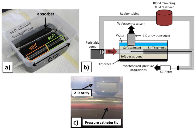
Fig. 1.

Experimental setup. a) Image of the phantom used in this study. b) Schematic of the experimental setup used in the phantom study with the pressure catheter inserted into the phantom’s lumen and the catheter tip placed beneath the 2-D array at the scanned location. Schematic depicts imaging of the soft phantom part. Imaging of the stiff part was performed by flipping the phantom so that the stiff part would be away from the fixed end of the phantom along the flow direction. c) Close-up of the 2-D array over the silicone phantom with the pressure catheter tip being within the volume of interest.
