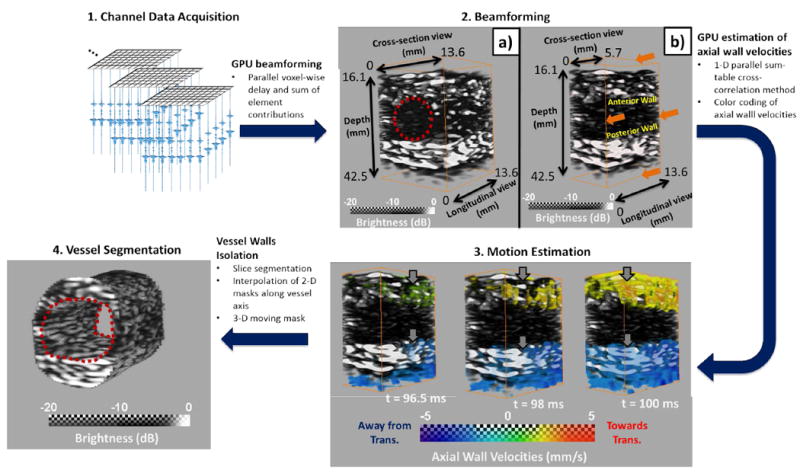
Fig. 2.

Illustration of the 4-D PWI post-processing methodology in the case of a silicone phantom. 1. Collection of channel data. 2. Beamforming of the channel data to generate sequences of 3-D RF volumes. 2a) Depicts a sample beamformed 3-D volume and 2b)shows a sub-volume by slicing close to the center of the imaged vessel. Red circle indicates the approximate position of the vessel 3. Sequence of 4-D PWI axial wall velocity (VPWI) volumes indicating the pulse wave propagation. Red indicates motion towards the transducer (top) and blue indicates motion away from it (bottom). Grey arrows indicate the progression of the pulse wave propagation. 4. Segmented vessel.
