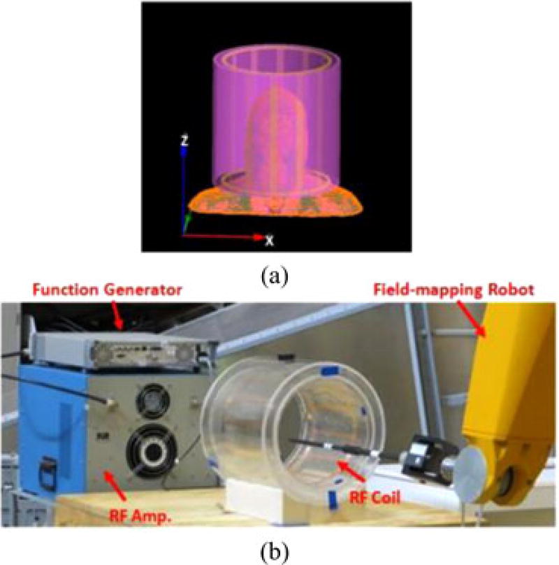
Fig. 1.
(a) Geometry of the 12-rod birdcage coil (yellow) with head model and cylindrical HDC material (violet) located outside of the coil used for numerical simulations. (b) Experimental setup showing the custom-made RF head coil with the external sleeve filled with distilled water. The RF amplifier and function generator used to feed the coil at 128 MHz is visible on the left, and on the right are visible the robotic system with one of the probes used for the measurements.

