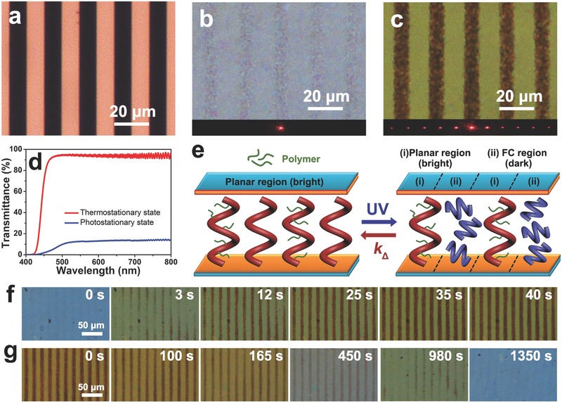
Figure 5.

a) Optical microscopy image of the stripe photomask for fabricating the motor‐doped PSCLC grating. POM images of the M1‐doped PSCLC with b) homogeneous planar configuration at the TSS and c) binary pattern (alternate planar and FC configuration) at the PSS. Diffraction patterns of laser beam (λ = 633 nm) at the “off” and “on” states on underside. d) Transmittance spectra of the M1‐doped PSCLC at the TSS and the PSS, respectively. e) Schematic illustrations of reversibly dynamical PSCLC grating at the corresponding states. f) POM images of PSCLC grating during photodynamic evolution at 80.0 mW cm−2 and g) thermodynamic evolution at room temperature.
