. 2018 Feb 19;8(14):7839–7846. doi: 10.1039/c7ra11943g

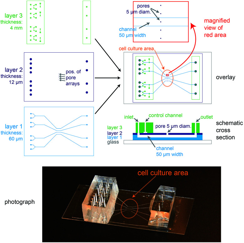
Fig. 1. Design of the microfluidic biochip. On the top left side, the designs of the three PDMS layers from which the chip is made are shown. The light blue areas in layer 1 correspond to channels, whereas the dark blue areas in layer 2 correspond to holes or pores. The green areas in layer 3 correspond to channels, and the star-shaped structures represent the position of access ports for tubing. In the overlay image (middle right) the fibronectin-coated cell culture area is outlined by an orange oval, the magnification (top right) shows how the pores are aligned above the channels and also a schematic cross section is depicted (bottom right). On the bottom a photograph of a completely assembled chip with a supporting glass cover slip is shown.

Fig. 1