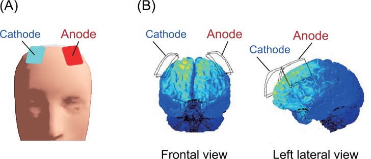
Fig 2. Electrode placement.
(A) Anodal (F3) and cathodal (F4) electrodes marked on the scalp surface. (B) The computational simulation of brain current flow during the delivery of the tDCS. Major changes in the brain current flow were observed in the dorsal-frontal areas during stimulation [37].

