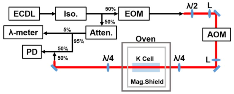
Fig. 1.

Instrument optical schematic. The abbreviated components are an external-cavity diode laser (ECDL), a fiber coupled isolator (Iso.), an electro-optic phase modulator (EOM), half-wave and quarter-wave plates (λ/2 and λ/4, respectively), 100 mm lenses (L), an acousto-optic modulator (AOM), a potassium cell (K Cell), a triply shielded magnetic chamber (Mag. Shield), a variable fiber attenuator (Atten.), a high precision wavelength meter (λ-meter), and a 1 GHz photodiode (PD). Fiber couplers are shown with their relevant split ratios. Only the 1st-order output of the AOM is shown (the 0th order is sent into a beam block). Fiber optics are shown in black while red lines denote free-space beam paths.
