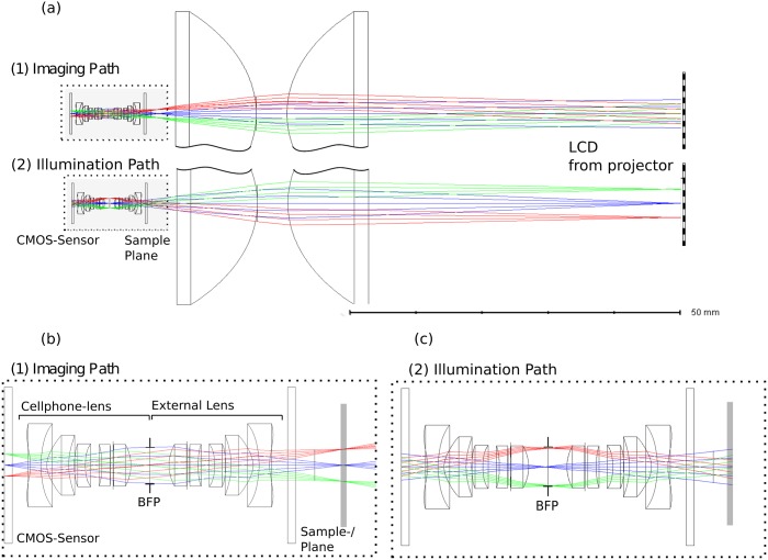
Fig 4. Optical Design of the illumination system.
(a) shows the microscope setup using an inversed camera-lens, the location of the sample-/slide- plane and the LCD from the video-projector. (b) shows the enlarged imaging path from (a), where the objects gets imaged onto the sensor. (c) shows, that the illumination system images the condenser aperture (e.g. the LCD) into the BFP of the microscope objective.

