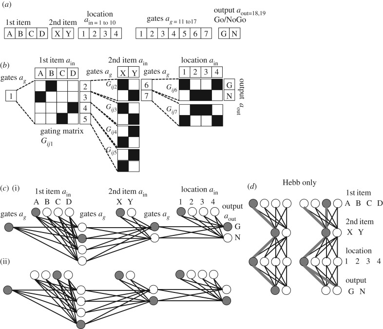
Figure 2.
Network structure. (a) The activity array used in simulations. Units are assigned to the first items A,B,C,D, second items X,Y, locations 1,2,3,4 and gates 1,2,3,4,5,6,7 and output Go, NoGo. (b) The network connectivity of gating in the model. Gate 1 regulates gated weights Gij1 between first patterns A,B,C or D and gates 2,3,4,5. Black squares indicate strengthened connections in a specific example of function also shown in figure 3. Gates 2,3,4,5 then regulate gated weights Gij2, Gij3, Gij4, Gij5 between second patterns X or Y and gates 6 or 7. Gates 6 or 7 then regulate gated weights Gij6 and Gij7 between location inputs 1,2,3 or 4 and outputs Go (G) or NoGo (N). (c) The same network connectivity as in b, but shown with circles representing units and lines (instead of matrices) representing weights. Filled circles represent active units for the examples described in the main text. (d) Example of a network without gating units or gated weights. Synapses between neurons representing patterns are strengthening with Hebbian modification only. This results in overlap for the association of pattern A with pattern X in location 1 versus pattern C with pattern X in location 1. The need for two different outputs cannot be accommodated in this structure.

