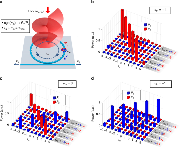
Fig. 7.
Proof-of-principle demonstration of spin-orbit jointly controlled unidirectional coupling of waveguide modes. a Schematic of platform for receiving CVVs via spin-orbit unidirectional coupling effect. For devices of unity transverse-spin states in the evanescent region (σres = ±1), the propagation direction of coupled light in the waveguide, or the ratio of received power at the two ports P1/P2, is first subject to the sign of incident SAM state, sgn(σin). Meanwhile, at a given wavelength (λres), the incident spin-orbit states 〈σin, lin〉 must obey the phase-matching condition lin + σin = lres for high-efficiency coupling. b–d Received power at Port 1 (P1, blue bars) and Port 2 (P2, red bars) of device WG4–10 when the SAM state of incident wave σin = +1, 0, and −1, respectively. For each σin, CVVs at 5 resonance wavelengths of WG4–10 (1578.61, 1583.11, 1587.59, 1592.11, and 1596.66 nm) and 11 OAM states (lin = −5, −4, …, and +5) are illuminated on the device. At these five wavelengths, the CVVs emitted from the device would carry the topological charges of lres = ±4, ±2, 0, ∓2, ∓4, respectively, when injecting light into Port 1 (2), as marked in blue (red) on the lres axis in b–d. All measured power has been calibrated with respect to the lensed fiber coupling loss (Supplementary Note 10), and all data are normalized to the highest value in each lres group

