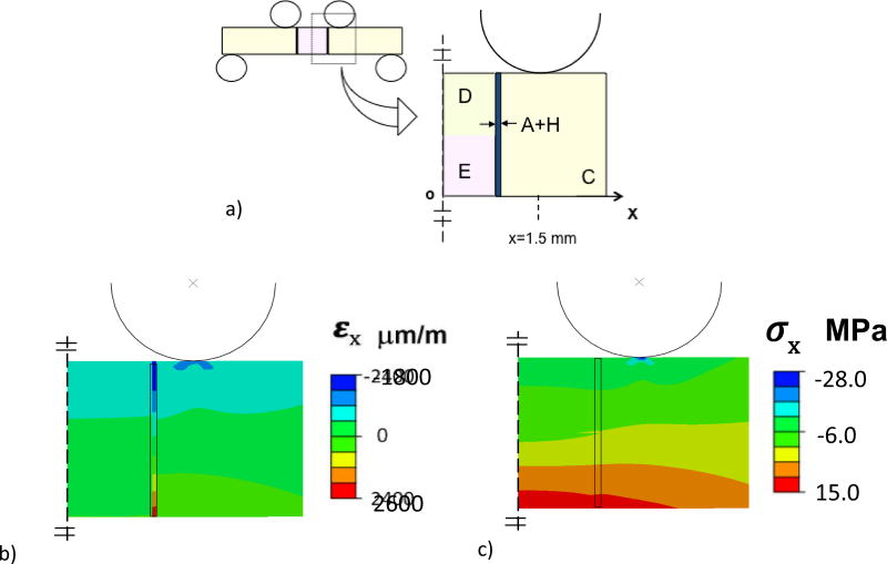
Figure 3.
Details of the Finite Element Analysis (FEA) for four-point loading of the bonded interface specimens with DEJ. The resin composite (C), enamel (E) and the twin bonded interfaces are highlighted, along with the resin adhesive and enamel hybrid layer (A+H). a) Model configuration. b) Normal strain distribution within the beam in the x direction. Red = tensile strain and Blue = compressive strain. c) Normal stress distribution of the beam in the x- direction. The strain and stress distributions in this figure resulted from 10 N load flexure load. Red = tensile stress and Blue = compressive stress.

