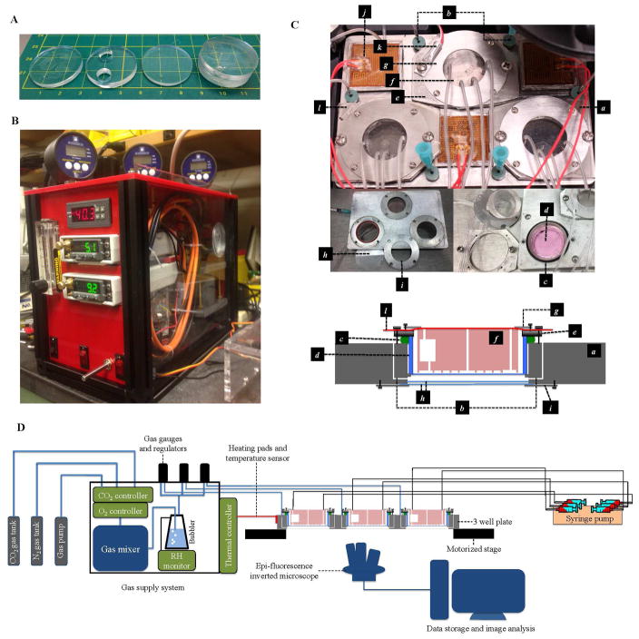
FIG. 3. The experimental setup.
(A) The PDMS device. From left to right: the patterned layer, the reservoir layer, the capping layer, and the assembled device. The three stacks of PDMS layers were bonded by oxygen plasma treatment. The reservoirs trap bubbles in the tubing. (B) The gas supply system. (C) The components of the customized 3 well sample plate. a, the main body of 3 well plate; b, a pair of gas channels that allow conditioned atmosphere to be pumped in and vented out through the septa at the entrance of the gas channels; c, an O-ring designed to seal the space between the well plate and the Lumox™ dish; d, the 35 mm diameter Lumox™ dish; e, the dish holder; f, the PDMS device; g, the PDMS chip holders; h, the double layer 35 mm glass windows designed to maintain thermal isolation and prevent water condensation; i, glass window holder; j, heating pads; k, temperature sensor; l, the Microseal™ B Adhesive Sealer (Biorad, Hercules, California 94547 USA) that keeps the chip from drying out. (D) The setup of the experiment, including the gas supply system, gas channels connection, the medium supply connection and the imaging system.

