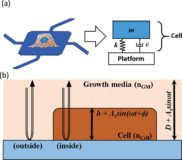
Fig. 1.

Schematic diagram of optomechanical stiffness measurement. (a) A cell on a sensor can be modelled as a spring-damper-mass system. (b) When the LDV laser is located inside the cell body, oscillation of the cell body modulates the optical path length of the LDV laser, causing the apparent shift of the measured velocity’s phase.
