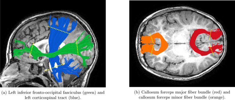
Figure 5. Bundle ROI placement for clipping endpoints on four different bundles.

Location of ROIs is indicated by yellow dotted line on each fiber bundle. This procedure was part of the pre-processing prior to the geometry modeling.

Location of ROIs is indicated by yellow dotted line on each fiber bundle. This procedure was part of the pre-processing prior to the geometry modeling.