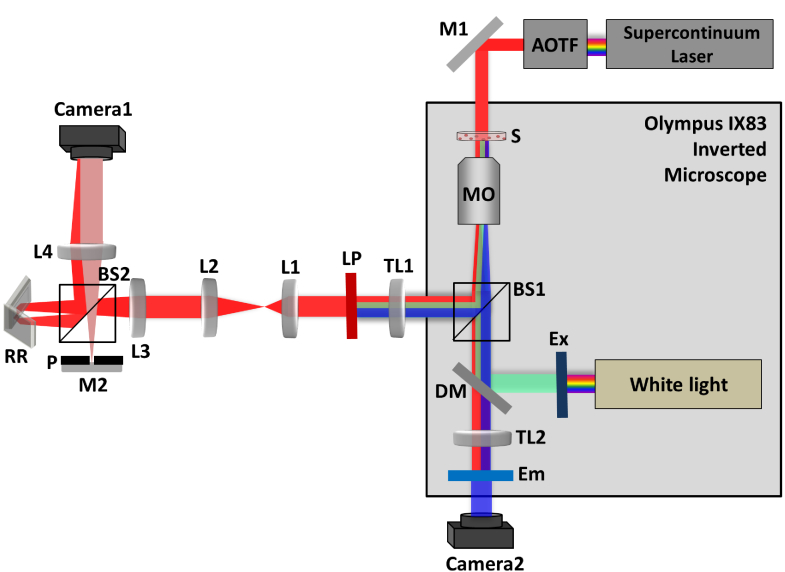
Fig. 6.
Scheme of the combined IPM-epifluorescence setup used for imaging. IPM beams appear in red; The fluorescent excitation beam appears in green; The fluorescent emission beam appears in blue. Ex, excitation filter; DM, dichroic mirror; Em, emission filter; AOTF, acousto optical tunable filter; BS1, BS2, beam splitters; M1, M2, mirrors; RR, retroreflector; S, sample; MO1, microscope objective; TL1, TL2, L1, L2, L3, L4, lenses; LP, long-pass filter; Camera1, Camera2, digital cameras.

