
Figure 1.
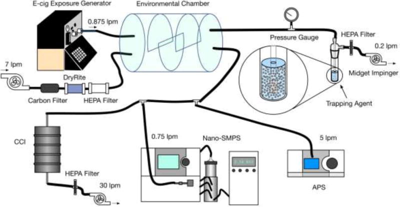
E-cig exposure generation system (Ecig-EGS, adapted from Zhao et al. (2016)) for ROS characterization. This schematic summarizes all tests and individual flow rates required for each test. CCI, SMPS, APS and the impinger were not used at the same time. For example, when impinger was used for sampling, it was used alone (CCI, SMPS and APS were not operated). A balance pump was used to balance the total input and output flow rate, when necessary.