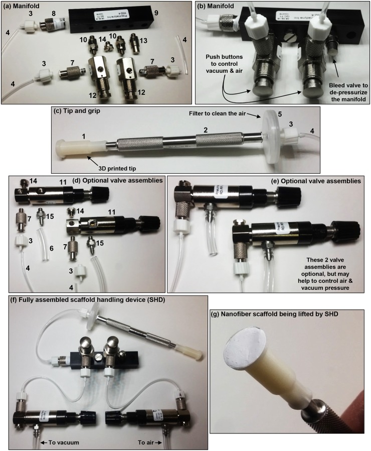
FIG. 3.
Assembly of the scaffold handling device (SHD) with the 12-mm dia. tip. The numbers in the photos refer to part numbers in Table I. (a) Parts used to assemble the manifold are laid out to approximately indicate how they should be assembled. (b) Assembled manifold. (c) Assembled tip and grip. (d) Parts used to make the optional valve assemblies are laid out to approximately indicate how they should be put together. (e) Valve assemblies. The valve assemblies are optional and may be used to help control pressure for the air and vacuum for the SHD. (f) Fully assembled SHD with optional valve assemblies. Note that short sections of tubing were used for the images so that the connections between the parts would be clear. Longer sections of tubing are needed as appropriate for actual use of the SHD. Teflon tape may be used on threads to reduce leakage. (g) SHD with a nanofiber scaffold on the tip under gentle vacuum.

