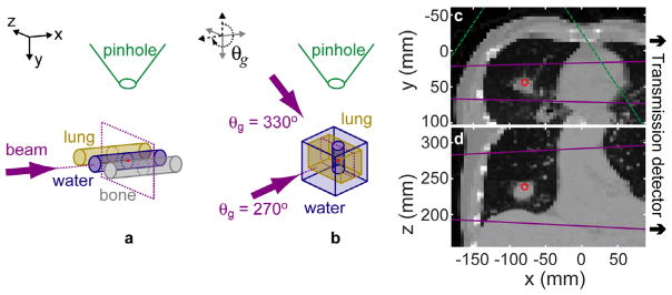
Figure 1.
The 3C phantom (a) consists of three 2.8 cm diameter, 7 cm long cylinders (ρlung = 0.29, ρwater = 1.00, ρbone = 1.824 g cm−3) with center-to-center spacing of 5.1 cm. The LT phantom (b) is formed by a vertical 2.8 cm diameter water cylinder of 7 cm length centered within a 9 × 9 × 11 cm3 lung box. The lung is surrounded on top, bottom, and back by a 2 cm layer of water and 4 cm of water in front (at the θg = 270° beam entrance). For variable LT source/gantry angles, the phantom and detector are fixed, and the source is rotated around the z axis (e.g. the θg = 330° beam direction is specified). The LTCT phantom axial (c) and coronal (d) slices are shown. The CT is down-sampled to a voxel size of 4.69 × 4.57 × 2 mm3. The isocenter is marked (red point). The beam direction ((a) and (b): arrows) and size ((c) and (d): lines) are marked (purple). The pinhole position ((a) and (b)) and field of view ((c): dashed lines) are marked (green). For all simulations, the source, pinhole, and detector plane were placed 100, 18.5, and 37 cm, respectively, from isocenter. The schematics in (a) and (b) are not to scale.

