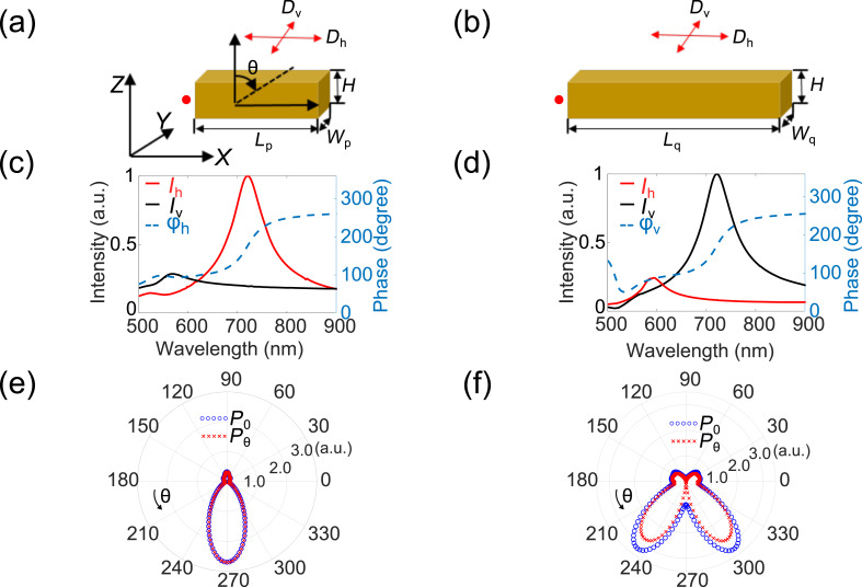
Figure 2.
Characteristics of the bar antenna excited by an electric dipole emitter. (a, b) Schematic of the simulation setup for the short bar (a) and the long bar (b) antenna, respectively. The red arrows represent point-dipole emitters with X or Y orientations. The red spots represent electric probes. (c, d) The electric field intensity (I) and phase (φ) at the position of the probe when point-dipole emitters oriented along X and Y are used as an excitation source for the short and long bar, respectively. The subscript h and v represents the field induced by the point-dipole emitter along X and Y directions, respectively. We only show phase information for the short bar excited by a X-orientated emitter (φh) and the long bar excited by a Y-oriented emitter (φv). The field intensity is normalized to the larger one for emitters with different orientations. (e, f) Polar plot of the total (P0) and azimuthal components (Pθ) of the far-field power distribution when the short bar is excited by a X-oriented dipole (e) and the long bar is excited by a Y-oriented dipole (f), respectively. The direction of θ is illustrated by arrows.

