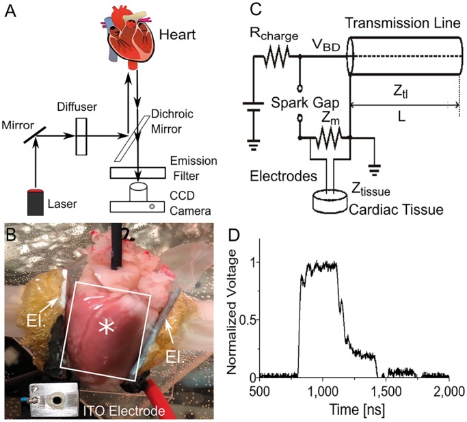
Figure 1.

Setup used in our defibrillation experiments. (A) Optical mapping setup. The heart is stained with the voltage-sensitive fluorescent probe Di-4-ANBDQBS and illuminated with a diffused laser at 671 nm. Fluorescent light is filtered with a long pass filter and recorded with a CCD camera. (B) Photograph of heart in setup. The electrodes are positioned to the left and to the right of the heart (see arrows labelled ‘El.’), illumination is from the top, and fluorescent light is also recorded from the top. Two aluminium plate electrodes touch the heart at the right and left ventricular free wall. Inset shows indium tin oxide (ITO) window electrode for observation of shock effects right under the electrode. A circular hole was drilled into the aluminium electrode and covered with glass that was coated with (electrically conductive) ITO. The label ‘asterisks’ indicates where the ITO electrode was located when it was used. The white rectangle indicates a typical field of view of the camera. (C) Spark gap generator for 300 ns shocks. (D) Experimentally determined shock waveform.
