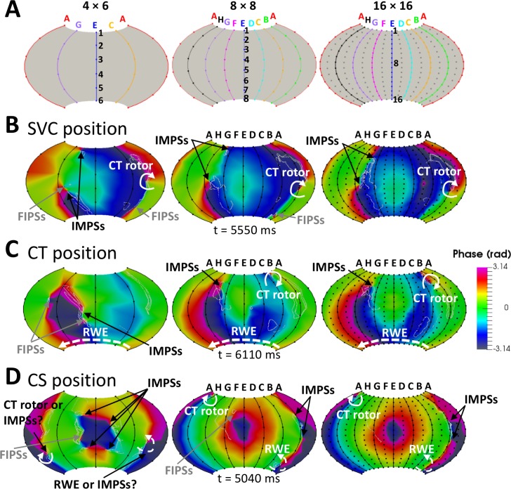
Fig 9. Effect of EGMs interpolation in the phase maps.
2D projection of the baskets (A) and phase maps for the SVC (B), CT (C) and CS (D) positions with a density of electrodes of 4×6 (left), 8×8 (middle) and 16×16 (right). IMPSs: imaginary phase singularities; FIPSs: false interpolation phase singularities; CT rotor: rotor along the crista terminalis; RWE: rotor wave extension.

