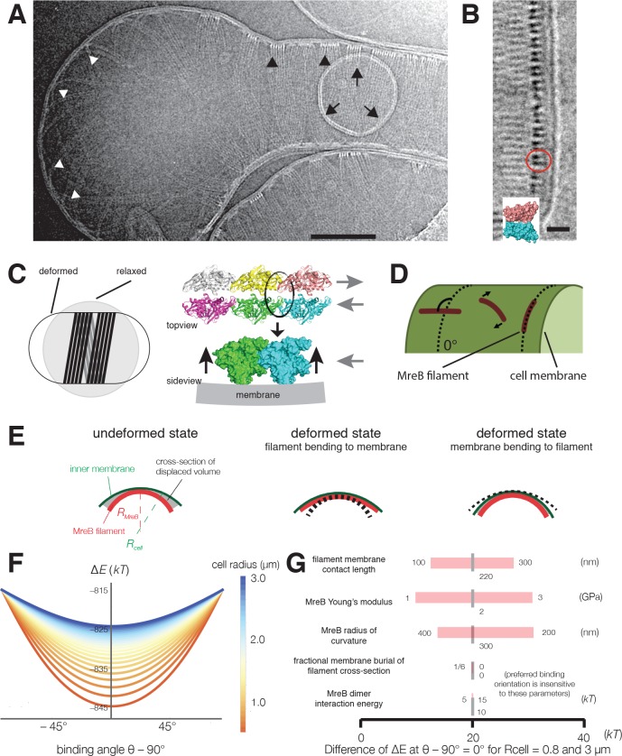
Figure 4. Cryoelectron tomography shows T. maritima MreB filaments assembled in liposomes align perpendicular to the rod axis.
(A) Cryoelectron tomography of T. maritima MreB filaments assembled inside liposomes. Black arrowheads show aligned bundles of filaments in a tubulated liposome, white arrowheads show unaligned bundles in a spherical region of the same liposome. Arrows show a positively curved surface inside the liposome, to which no MreB filaments bind. Scale bar is 100 nm. See also Figure 4—figure supplement 1. (B) Zoomed in view of MreB filaments within a tubulated liposome shows MreB adopts a double-stranded antiparallel protofilament arrangement (dark lobes), consistent with previous models of MreB monomer interactions (colored structure in inset) (van den Ent et al., 2014). The red circle indicates the cross-section of an MreB filament, modelled in the inset. Scale bar is 50 nm. (C) (left) Schematic drawing depicting the cause of the shape change from spherical to rod-shaped liposomes: MreB wants to attain greater curvature and since there are many filaments, they are laterally stabilized. As the liposome is much more easily deformable than cells, the resulting energy minimum is a deformed liposome with an MreB helix on the inside. (right) Model showing why the unusual architecture of MreB filaments might have been selected during evolution: its juxtaposed subunits in the two antiparallel protofilaments produce putative hinges that could be the region of bending for these filaments. Canonical F-actin filament architectures, with staggered subunits, would need bending within the subunits, which is less easily achieved. Modeling of MreB – membrane interactions and filament orientation. (D, E) Hydrophobic residues are located on the outer edge of the antiparallel MreB double filament, which is here modeled as an elastic cylindrical rod. To achieve maximum hydrophobic burial, membrane deformation, MreB bending, or a combination of the two may occur. (F) A plot of the change in total energy (∆E) caused by the MreB-membrane interaction against the binding angle θ for various cell radii shown in the color scheme on the right. Note that ∆E is minimal at θ = 90°, which agrees with the observed orientation of MreB binding and motion. At larger rod radii, the energetic well becomes flatter and MreB binding becomes more susceptible to thermal fluctuations and other sources of stochasticity, which would result in a broader angular distribution of filaments. (G) A sensitivity analysis of the model over a range of model parameters.


