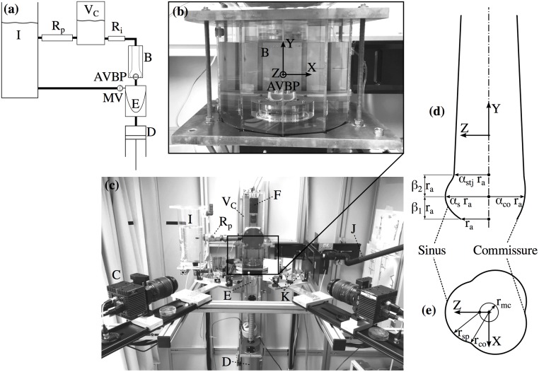
Fig 1. Experimental setup and aortic root scheme.
Schematic of the flow loop (a). Test cell (b) containing the AVBP and the silicone phantom (B, immersed in blood analog fluid). Experimental setup (c) showing the CCD Cameras for TOMO PIV (C) and POA measurements (F); the piston pump (D) controlling the contraction and expansion of the silicone ventricle (E); elements of the flow loop: the compliance chamber with air volume VC, the peripheral resistance Rp, and the tank (I); a light guide for volume illumination with a Nd:YAG laser (J); and the mirror setup for view-doubling (K). Parametrization of the aortic root (d) in axial plane at X = 0. Parametrization of SOV (e) in a cross-section at β1ra above the annulus.

