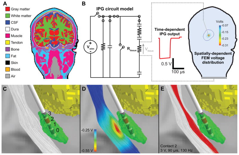
Figure 5.
Computational model of DBS. A) We created a 3-dimensional finite element model (FEM) of DBS using an anatomical model of a human head and neck. B) We used the circuit models to estimate the time dependence and the FEM to calculate the spatial dependence of the tissue voltage (Vtissue). C) The DBS model included 1000 descending corticofugal fibers and a DBS lead implanted in the subthalamic nucleus (STN). D) The voltage distribution generated by −3 V applied through contact 2 interpolated onto the corticofugal fibers. E) For the IPG model, the corticofugal fibers shown in red were activated by monopolar stimulation applied through contact 2 with the following parameters: pulse amplitude = 3 V, pulse width = 90 μs, pulse frequency = 130 Hz, and electrode impedance = 1 kΩ.

