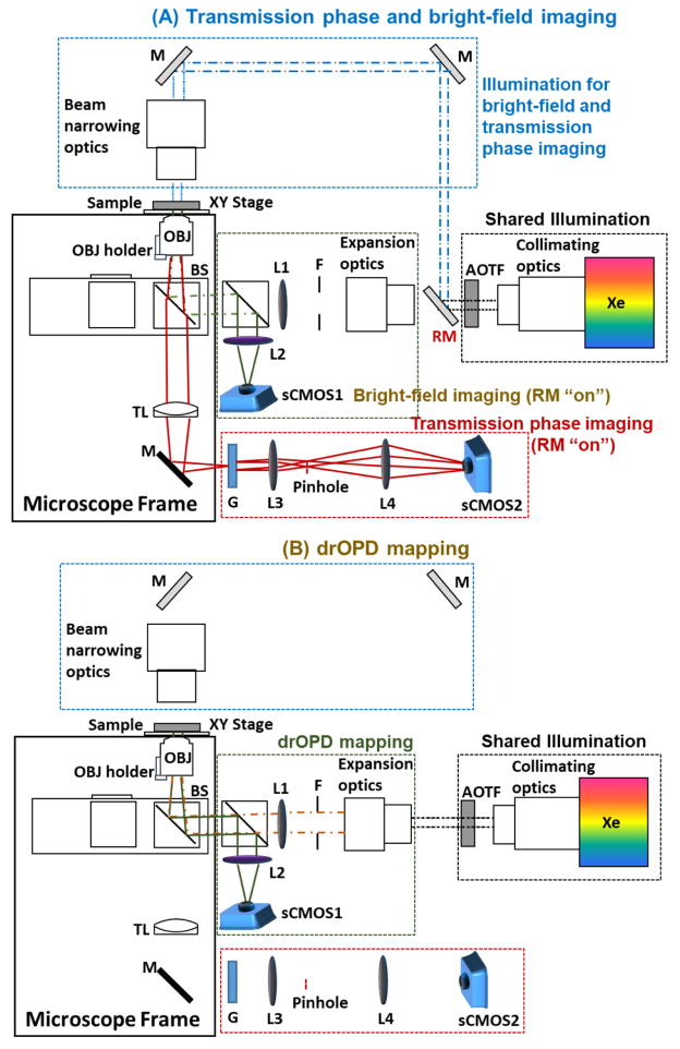
Figure 6.
The schematic of the nanoNAM system. (A) The light path diagram for transmission phase and bright-field imaging. (B) The light path diagram for drOPD mapping. Xe: Xenon lamp; RM: removable mirror; F: field diaphragm; L: lens; BS: beam splitter; OBJ: objective; TL: tube lens; M: mirror; G: transmission grating.

