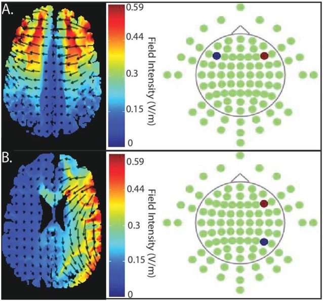
Figure 2.

Current flow model of targeted stimulation sites. (A) Simulation of bilateral stimulation to prefrontal cortex. Electrodes placed in PFC-PFC (anode (red) placed intermediate between F4 and F8, cathode (blue) placed intermediate between F3 and F7). (B) Simulation of unilateral stimulation, which the anode (red) is, situated over right PFC (centered intermediately between F4 and F8) and the cathode (blue) over right posterior parietal cortex (PPC; centered between P4 and P8).
