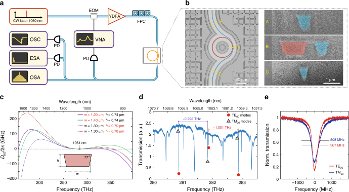
Fig. 1.
Si3N4 microresonators for soliton frequency comb generation in the NIR. a Set-up schematic used for dissipative Kerr soliton generation and characterisation: a tunable external-cavity diode laser with a centre wavelength of 1050 nm is used as a seed, YDFA – ytterbium-doped fibre amplifier, FPC – fibre polarisation controller, VNA – vector network analyser, EOM – electro-optical phase modulator, PD – photodiode, OSC – oscilloscope, ESA – electrical spectrum analyser, OSA – optical spectrum analyser. b Left: optical microscope image of the 1-THz microring resonator (highlighted in red) with a pulley-style bus waveguide (blue). Right: scanning electron microscope images of the resonator and bus waveguide cross sections obtained via focused ion beam cuts at different positions (A–C) marked on the left image. c Simulated integrated dispersion profiles (Dint/2π) for TM00 mode of resonator waveguides having different heights of 0.70, 0.74 and 0.78 μm, widths of 1.2, 1.3 and 1.4 μm and fixed sidewall angle of 77° (see more details on dispersion engineering in Supplementary Note 1). d Transmission trace of the 1-THz microresonator shown in (b). The two fundamental mode families (TE00 and TM00) can be distinguished based on their free spectral ranges (0.992 THz for TM00 and 1.001 THz for TE00), and are marked with red and blue shapes correspondingly. Other resonances correspond to higher order modes with comparably lower Q-factors. e Linewidth measurements of the fundamental mode families. The frequency axis was calibrated using a fibre-loop cavity. Typical loaded linewidth of the modes is ~400 MHz for TE00 and ~500 MHz for TM00

