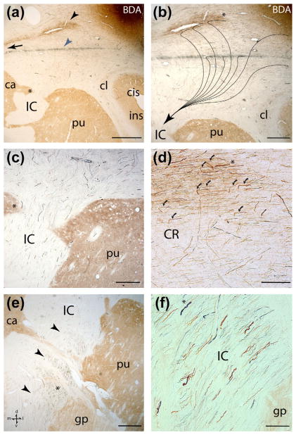
FIGURE 9.
Photomicrographic plate showing immunohistochemically labeled fibers from case SDM32, which had two injection sites in the M1 orofacial representation (see Figure 8, top right, for lateral cortical surface view of the injection sites). All sections are in the coronal plane and the anatomical orientation shown in the bottom left of panel e applies to all panels. The brown colored fibers are from the more dorsally located BDA injection site and the blue fibers are from the more ventrally located FD injection site. (a) Low power coronal section depicting the main BDA labeled fiber bundle (black arrowhead) and FD labeled fiber bundle (blue arrowhead) traveling in the corona radiata and arching over the putamen (pu). Note the dorsal to ventral location of the respective labeled fiber bundles and distinct spatial separation between the main fascicles. The black arrow identifies the path direction toward the corpus callosum where both fiber bundles eventually cross the midline. The asterisk is for anatomical orientation of panel c, which shows greater detail of the descending labeled fibers in this location but at a higher magnification. (b) Higher magnification of panel a showing the complex, and multifaceted nature of fibers leaving the main BDA labeled fiber bundle and FD labeled fiber bundle to enter the IC. Although the fibers emerge from each main bundle from many micro orientations, the superimposed trajectories (fine black lines leading to the arrowhead) illustrate some curvilinear and angulated trajectories taken by fibers destine to reach the IC. The asterisk adjacent to the main BDA (brown) labeled fiber pathway is for anatomical orientation of panel d, which shows greater detail of the descending labeled fibers in this location but at a higher magnification. (c) Photomicrograph showing FD labeled (blue) and BDA labeled (brown) fibers at superior levels of the IC. The anatomical location of this image is demarcated in panel a (see asterisk). (d) Higher power photomicrograph of BDA labeled fibers leaving the main fiber bundle in the corona radiata (CR). The anatomical location of this image is demarcated in panel b (see asterisk). Note the sharp angles taken by the fibers (curved arrows) as they abruptly changed their trajectory downward en route to the IC. This general pattern of fiber trajectory was also characteristic of fibers traveling from the LPMCv injection sites as they coursed in the CR to enter the IC. (e) Photomicrograph showing the descending fibers from the M1 orofacial injection sites at mid-levels of the IC as they descend near the medial border of the putamen and globus pallidus. Note how the main bundle of fibers occupy the lateral half of the IC (arrow heads). The asterisk is for anatomical orientation of panel f, which shows higher magnification of the labeled fibers in this location. (f) High power photomicrograph of fibers in the IC (anatomical location shown in panel e) illustrating the commixed nature of blue and brown labeled fibers from tracer injections in the ventral and dorsal regions of the M1 orofacial representation. Scale bar =2 mm in a; 1 mm in b; 500 μm in c; 250 μm in d; 1 mm in e; 100 μm in f. BDA =biotinylated dextran amine; ca =caudate nucleus; cis =circular sulcus; cl =claustrum; CR =corona radiata; gp =globus pallidus; IC =internal capsule; ins =insula; pu =putamen

