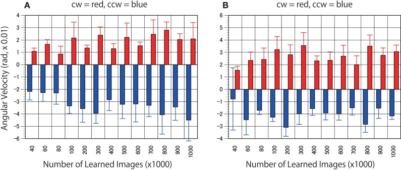
Figure 4.
Predicted motion found in the rotating propellers. (A) Optical flow vectors detected between a pair of the first/second consecutive predictive images (P1/P2) of the rotating propellers (15 rpm). (B) Mirrored images of the rotating propellers were used as test stimuli. In other words, the cw of A and the ccw of B are derived from the same video, and the ccw of (A) and the cw of (B) are derived from the same video. Six optical flow vectors were detected in each pair of predicted images. Mean angular velocity was calculated from the optical flow vectors. A positive sign was assigned to clockwise rotation. The results of the clockwise propeller are presented in red, and the results of the counter-clockwise propeller are presented in blue. The rotation rate of 15 rpm is approximately comparable to 5.23 rad (× 0.01). Error bars indicate standard errors, and the slanted zero horizontal lines appear to a kind of café wall illusion.

