
Figure 4.
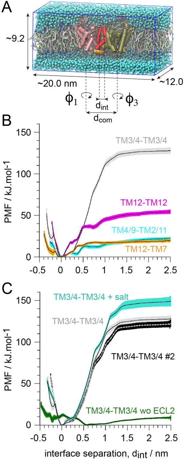
Comparative strength of hSERT dimer interfaces. (A) Simulation setup. The transporters transmembrane helices (TM) are shown in tan and pink tubes, but TM11 and TM12 are black and red, respectively, and the C-terminus helix in orange. (B) Potentials of mean forces (PMF) of the different hSERT interfaces formed in the self-assembly simulations. (C) PMFs of the TM3/4 interface variant: the original TM3/4 and a repeat (#2), in presence of 0.2 M of NaCl (+salt) and with the interaction of the ECL2 between the two monomers removed (wo ECL2).