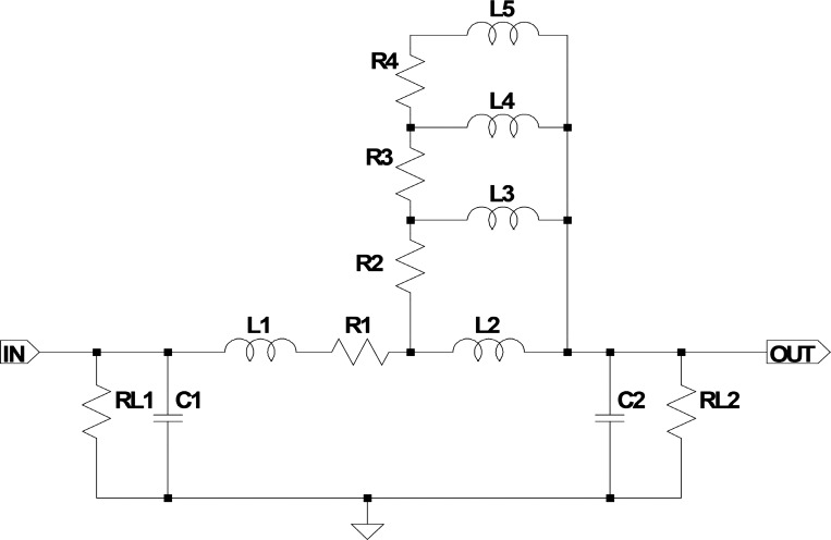
Fig. 2.
Electrical representation of a segment of an artery in the original Westerhof model. R1 . . . . n: resistances represent the series (conduit) resistances acting against the flow of blood in the arteries and are mainly influenced by the square arterial diameter and viscosity. L1 . . . n: inductors represent the inertial properties of blood and are dependent on blood density and arterial diameter. C1 . . . n: capacitors represent the compliant properties of the arteries, mainly influenced by the elastic modulus of the arterial walls, arterial radius, and wall thickness. RL1 and RL2: load resistances (leakage resistances). R2 to R4 and L2 to L5 refer to the Westerhof correction network. A detailed description of the electrical-physiological analogy can be found in Ref. 18 on page 124.

