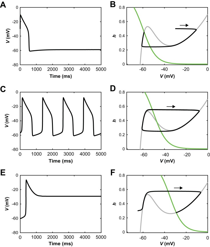
Fig. 2.
Schematic illustration of operating regimes for an uncoupled reduced model unit. A, C, and E: voltage time courses. B, D, and F: corresponding phase plane representations, each including V-nullcline (dV/dt = 0, gray), h-nullcline (dh/dt = 0, green), and trajectory (black). Each trajectory evolves clockwise. A and B: when the h-nullcline intersects the left branch of the V-nullcline, trajectories converge to a stable steady state at hyperpolarized voltage. C and D: when the h-nullcline intersects the middle branch of the V-nullcline, relaxation oscillations result. E and F: when the h-nullcline intersects the right branch of the V-nullcline, trajectories converge to a stable steady state at depolarized voltage.

