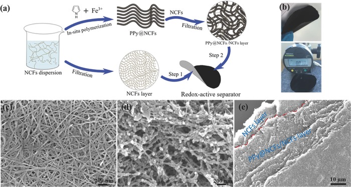
Figure 2.

Fabrication and morphological characteristics of the redox‐active separator. a) Schematic illustration of the preparation of the redox‐active separator. b) Photos of the flexible redox‐active separator. c) SEM image of the NCF layer. d) SEM image of the PPy‐containing layer.e) SEM image of a torn redox‐active separator.
