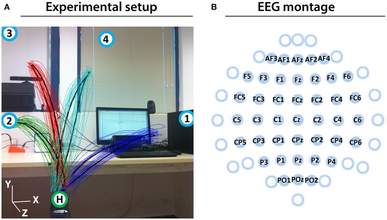
Figure 1.
Experimental setup and EEG montage. (A) Experimental setup including an overlaid image of the 3D trajectory of the registered (colored thin curves) and averaged (black thick curves) arm movements between the home position (green circle with H) and four target positions (blue circles with numbers) of a representative subject (Subject 1). (B) The channels that were used as center points for the Laplace filtering and optimal MTP parameter selection are labeled (non-labeled channels were used only as side electrodes for the corresponding Laplace filter center positions, where required).

