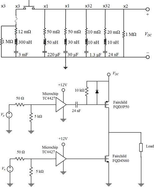
Fig. 1.

(Top) The electrical schematic for the capacitor array, including parasitic values for the capacitors. The array is connected between high-voltage (VDC) and ground. The multiplier above each series RLC indicates the number of parallel units used in the full array. (Bottom) A schematic of one unit of the amplifier system. The complete amplifier comprises 8 channels and each channel consists of 4 identical units in parallel between the input signals (Vn, Vp) and the output to the load.
