
Figure 3.
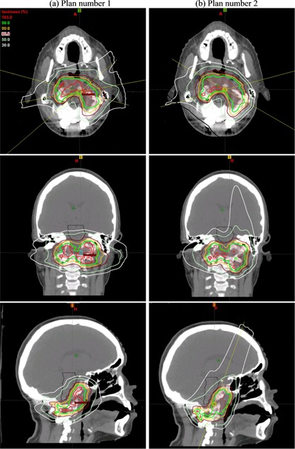
Axial, corolla, and sagittal view of two initial spot scanning beam plans. Plan number 1 (a) is on the left and plan number 2 (b) is on the right. The axial view of Fig. 3(a) shows the angle of left anterior oblique (LAO), right posterior oblique (RPO) and left posterior oblique (LPO) beams in plan 1. The angle of the RPO and right anterior oblique RAO beams in plan 2 can be seen in the axial view of Fig. 3(b) and the angle of vertex beam can be seen in the sagittal view of Fig. 3(b).